
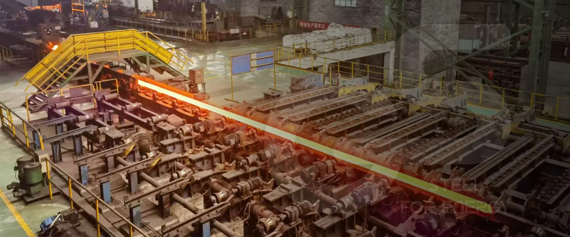
Production tubing is the steel pipe string that carries oil, gas, and injection fluids between the reservoir and the wellhead in an oil or gas well. Every producing well has tubing — it is the working pipe of the completion, directly exposed to produced fluids throughout the well's producing life. Tubing grade selection, sizing, and connection specification are critical completion engineering decisions that directly affect well productivity, corrosion management, and workover frequency.
ZC Steel Pipe supplies API 5CT production tubing across the full grade range from J55 through C110, including L80-13Cr for CO2 service, with EUE, NUE, and premium connections. We see purchase orders for production tubing from operators in Southeast Asia, the Middle East, and West Africa on a regular basis — and the misspecification patterns repeat across markets. This guide covers what production tubing does, how grades are selected, sizing, connections, sour service requirements, and the procurement mistakes that result in the wrong pipe being shipped.
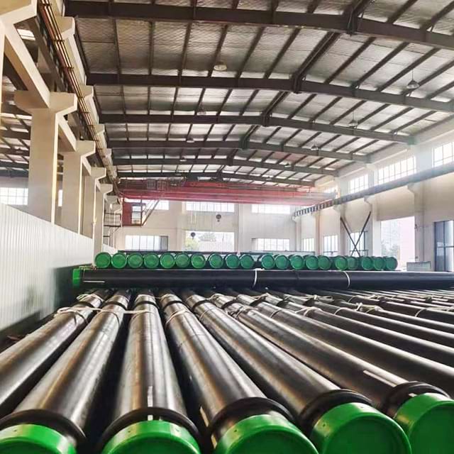 Racks of finished tubing with green thread-protector caps in the ZC production hall.
What we see on CO2/H₂S enquiries: In CO2 gas condensate tubing enquiries from Southeast Asia and the Middle East, the most common misspecification we see is L80-13Cr ordered for wells where the fluid analysis shows "CO2 dominant, trace H₂S." L80-13Cr's passive chromium oxide film gives excellent CO2 corrosion protection — but the same passive film concentrates atomic hydrogen at the metal surface in H₂S environments, making L80-13Cr more susceptible to sulfide stress cracking than plain L80-1 carbon steel in the same well. The chromium content that solves one problem creates a more severe version of the other.
1. What Production Tubing Does
Production tubing serves as the conduit between the producing formation and the surface.
In producing wells: Reservoir fluids (oil, gas, water) flow from the perforations through the tubing bore to the wellhead. The tubing string is set on a packer that seals the annulus between tubing and casing, forcing all production through the tubing.
In injection wells: Water, gas, or other fluids are pumped down the tubing into the reservoir. The packer isolates the injection zone and prevents fluid from entering the casing annulus.
During workovers: Unlike casing, tubing can be pulled (retrieved) from the well using a workover rig. This allows inspection, replacement of corroded or damaged tubing, changes to completion configuration, and re-perforation of new zones. The retrievable nature of tubing is the reason grade selection matters so much — a corroded or failed tubing string requires a workover that costs more than the original material.
2. Tubing vs Casing — Key Differences
| Property | Production Tubing | Production Casing |
|---|---|---|
| OD range | 1.9″ – 4-1/2″ | 4-1/2″ – 20″ |
| Function | Fluid conduit — producible | Wellbore structural liner |
| Cement | No | Yes — cemented in annulus |
| Retrievable | Yes | No |
| Connection | EUE, NUE, premium | BTC, premium |
| Exposure to fluids | Direct — all produced fluid | Annular fluid only |
| Design load | Internal pressure, corrosion | Collapse, burst, tension |
| Design life | Workover-dependent | Well life (permanent) |
The table captures the core asymmetry: casing sees wellbore loads and is designed to resist collapse and maintain wellbore integrity; tubing sees produced fluid chemistry and is designed to resist corrosion, internal pressure, and the tensile load of its own weight in long strings. A 4,000m tubing string in 2-7/8" 6.40 lb/ft weighs roughly 38 tonnes — the connection tensile rating becomes a critical check at those depths. For where tubing sits in the wider tubular family, see what is OCTG pipe.
For the complete grade ladder with tensile, hardness, and chemistry limits, see the API 5CT specification tables →
To match a grade to your well conditions, use the Pipe Grade Selector →
3. API 5CT Tubing Grades
| Grade | Min Yield (MPa) | Min Yield (ksi) | Min Tensile (MPa) | Min Tensile (ksi) | Max Hardness | Sour Service | Primary Application |
|---|---|---|---|---|---|---|---|
| J55 | 379 | 55 | 517 | 75 | None | No | Shallow sweet oil wells |
| N80-1 | 552 | 80 | 689 | 100 | None | No | Moderate depth sweet service |
| L80-1 | 552 | 80 | 655 | 95 | 23.0 HRC | Yes | Sour service oil wells |
| L80-13Cr | 552 | 80 | 655 | 95 | 23.0 HRC | Limited | CO2-corrosive gas condensate |
| T95 | 655 | 95 | 724 | 105 | 25.4 HRC | Yes | Deep sour service |
| P110 | 758 | 110 | 862 | 125 | None | No | Deep sweet HPHT wells |
| C110 | 758 | 110 | 793 | 115 | 30.0 HRC | Yes | Severe sour HPHT wells |
Reading the table: the progression from J55 to P110 follows increasing yield strength — and for burst and tension calculations, yield strength is the primary variable. J55's 379 MPa sits at less than half P110's 758 MPa. For identical geometry, burst rating doubles as you move from J55 to P110. What the table also shows is where sour service qualification cuts in: L80-1, T95, and C110 all carry hardness limits (the mechanism for NACE MR0175 compliance), while J55, N80, and P110 do not. N80 for sour service is a common ordering error — the hardness is not controlled.
4. Grade Selection Impact on Burst Rating — Worked Barlow Calculation
The burst rating difference between grades is significant enough to drive completion design. For 2-7/8" 6.40 lb/ft EUE tubing — the most widely used production tubing size globally — the geometry is fixed: OD = 73.02 mm (2.875 in), wall t = 5.51 mm (0.217 in).
Barlow burst formula per API 5C3: P_burst = 0.875 × (2 × SMYS × t / D)
The 0.875 factor is the API 5C3 mill tolerance derating applied to all burst calculations.
Grade Selection Impact on Burst Rating — 2-7/8" 6.40 lb/ft EUE Tubing
| Grade | SMYS (ksi) | SMYS (MPa) | Burst Rating (psi) | Burst Rating (MPa) |
|---|---|---|---|---|
| J55 | 55 | 379 | 7,264 | 50.1 |
| N80 / L80 | 80 | 552 | 10,562 | 72.8 |
| T95 | 95 | 655 | 12,542 | 86.5 |
| P110 | 110 | 758 | 14,525 | 100.2 |
The 2× improvement from J55 (7,264 psi) to P110 (14,525 psi) is driven entirely by yield strength — the wall thickness and OD are identical for all four grades in the 2-7/8" 6.40 lb/ft weight class. This matters practically: a well with a tubing head pressure design requirement of 10,000 psi rules out J55 on burst alone and places N80/L80 right at the limit. The engineering margin disappears at 10,562 psi, meaning N80 has essentially no safety factor for burst at that design pressure. T95 at 12,542 psi provides a 25% margin; P110 at 14,525 psi provides 45%.
Use the Barlow pressure calculator → to check ratings for your specific OD, wall, and grade.
5. Standard Tubing Sizes
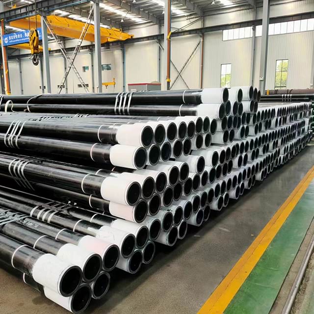 Tubing bundles with couplings made up on the box ends, staged inside the ZC mill.
Common production tubing dimensions (EUE connection):
| OD (in) | OD (mm) | Weight (lb/ft) | Wall (mm) | ID (mm) | Drift (mm) | Coupling OD (mm) |
|---|---|---|---|---|---|---|
| 1.900 | 48.3 | 2.75 | 3.68 | 40.90 | 39.8 | 60.3 |
| 1.900 | 48.3 | 3.65 | 5.08 | 38.10 | 37.2 | 60.3 |
| 2-3/8 | 60.3 | 4.60 | 4.83 | 50.66 | 51.1 | 73.0 |
| 2-3/8 | 60.3 | 5.80 | 6.45 | 47.42 | 47.1 | 73.0 |
| 2-7/8 | 73.0 | 6.40 | 5.51 | 62.0 | 59.8 | 88.9 |
| 2-7/8 | 73.0 | 8.60 | 7.82 | 57.78 | 58.0 | 88.9 |
| 3-1/2 | 88.9 | 7.70 | 5.49 | 77.9 | 75.8 | 108.0 |
| 3-1/2 | 88.9 | 9.20 | 6.45 | 76.0 | 73.8 | 108.0 |
| 4 | 101.6 | 9.50 | 5.74 | 90.1 | 88.0 | 120.7 |
| 4-1/2 | 114.3 | 9.50 | 5.21 | 103.9 | 101.6 | 132.1 |
| 4-1/2 | 114.3 | 11.60 | 6.35 | 101.6 | 99.3 | 132.1 |
Two columns deserve attention before sending a PO. The coupling OD column matters for packer compatibility — EUE coupling OD is meaningfully larger than pipe body OD (88.9 mm coupling vs 73.0 mm body for 2-7/8"). If the completion design specifies a packer with a 85 mm minimum bore, 2-7/8" EUE will not pass. The drift column matters for tool running — the drift diameter is the guaranteed minimum ID after drifting at the mill, and it must accommodate all wireline and coiled tubing tools run in the well.
Most used globally: 2-7/8 inch 6.40 lb/ft N80 or L80 EUE — the standard production tubing for conventional oil wells.
6. Connection Types for Production Tubing
The three tubing connection families and their tensile-efficiency and clearance tradeoffs are covered in full in the API 5CT tubing connections guide — EUE, NUE and integral joint.
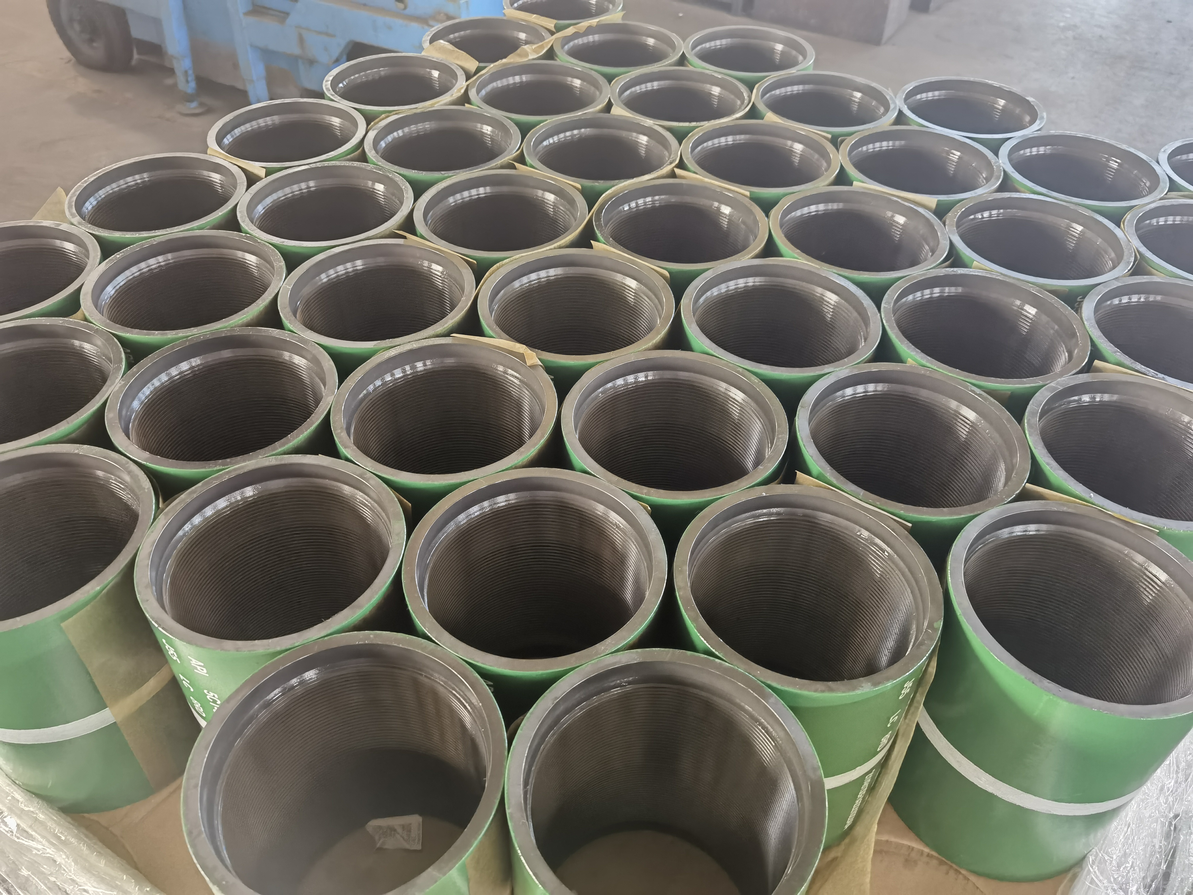 Couplings standing on end with internal threads visible — from a ZC N80Q/J55 coupling supply to a South America operator.
EUE (External Upset End) — Standard: The pipe ends are hot-upset (enlarged OD) to accommodate the longer thread engagement. 8-round thread, 8 TPI. Coupling OD is larger than pipe body OD — check clearance through packer bore before specifying. EUE provides 85–95% of pipe body tensile efficiency.
NUE (Non-Upset End) — Tight clearance: No upsetting — coupling OD is only slightly larger than pipe body. Used where clearance inside the casing or through downhole equipment is restricted. Lower tensile efficiency than EUE (~65–75% of pipe body). NUE tensile rating is a constraint at depth — a 3,000m NUE string should be checked against the hanging weight of the string.
Premium connections — Gas wells and HPHT: Metal-to-metal seal providing gas-tight performance. Required for: gas producers; HPHT wells; deviated wells with combined loading; CRA grades (13Cr, Super 13Cr); and any application where EUE capability is insufficient. VAM TOP, Tenaris Blue, and equivalent ISO 13679 CAL IV connections are the industry standard for gas-tight tubing service. For choosing a premium connection under combined HPHT, sour, and deviated loads, see the connection selection guide for HPHT, sour and deviated wells.
EUE 8-round thread is not gas-tight — the thread compound is the only seal, and at elevated temperature or pressure cycling the compound flows out of the thread form. API 5CT does not rate EUE for gas service, and every major gas operator's design standard requires premium metal-to-metal seal connections for gas producers. The distinction matters at procurement: an EUE tubing PO for a gas condensate well is technically non-conforming to operator engineering standards even if the pipe itself is within spec. If the well produces any significant gas phase, EUE needs to be upgraded to premium before the purchase order is issued, not after the well has been completed.
7. Grade Selection by Well Type
| Well Condition | Tubing Grade | Connection | Notes |
|---|---|---|---|
| Shallow sweet oil (<2,000m) | J55 or N80 | EUE | Cost-optimised; verify J55 collapse for gas lift |
| Standard sweet oil | N80 | EUE | Most common globally |
| Sour oil (H₂S present) | L80-1 | EUE or premium | NACE MR0175 required; not N80 |
| CO2 gas condensate | L80-13Cr | Premium mandatory | CO2 corrosion protection |
| CO2 + H₂S | Super 13Cr or duplex | Premium mandatory | Verify ISO 15156-3 |
| Deep sweet HPHT | P110 | Premium mandatory | High burst loads |
| Severe sour HPHT | C110 | Premium mandatory | Most demanding |
| Gas storage (high cycle) | L80 or T95 | Premium (high cycle) | Fatigue resistance |
| Deviated/horizontal | L80 or higher | Premium recommended | Bending loads |
| Gas lift well | N80 or L80 | EUE | Check collapse rating at max GL injection pressure |
The "CO2 + H₂S" row is where most misspecifications originate. When the fluid analysis shows CO2 as the dominant corrosive species, the instinct is to specify L80-13Cr for its chromium content. But if any H₂S is present above NACE MR0175 / ISO 15156 thresholds (typically 0.0003 MPa partial pressure), 13Cr is the wrong grade — and the failure mode is faster and more catastrophic than the CO2 corrosion it was designed to prevent. Work through the OCTG sour service grade selection guide before committing to a CRA grade in any H₂S-bearing well.
8. Named Failure Modes
Failure Mode 1: L80-13Cr in H₂S Service — SSC via Hydrogen Trap
Mechanism: L80-13Cr's 13% chromium content forms a passive oxide film that resists CO2-driven iron carbonate dissolution. In the presence of H₂S, however, the passive film acts as a diffusion barrier that increases the concentration of atomic hydrogen at the steel surface rather than allowing it to recombine and escape as H₂ gas. The result is elevated hydrogen fugacity at the metal-film interface, driving hydrogen into the steel lattice and promoting sulfide stress cracking at stress concentrators such as thread roots and coupling shoulders. L80-13Cr fails by SSC in H₂S environments where plain L80-1 carbon steel would remain stable.
Diagnostic: Cracking at connections early in well life, with H₂S detected in produced fluid. Metallurgical examination shows branched intergranular cracking consistent with SSC or HIC. Well fluid analysis shows H₂S partial pressure above the NACE MR0175 threshold (typically 0.0003 MPa / 0.05 psi for sour service classification).
Fix: For wells with both CO2 and H₂S, use the dominant corrosion mechanism to drive grade selection. If H₂S partial pressure meets NACE sour-service criteria, specify L80-1 (not L80-13Cr) for sour service and add a corrosion inhibitor program for CO2 protection. If CO2 is dominant and H₂S is trace, confirm H₂S partial pressure is below NACE thresholds before specifying L80-13Cr.
Failure Mode 2: EUE Tubing Gas Leak — Thread Compound Failure
Mechanism: EUE 8-round thread seals by compressed thread compound in the helical thread path. Gas molecules at high pressure pass through any discontinuity in the compound layer — an over-torqued connection that extrudes compound, an under-torqued connection with incomplete contact, or a connection torqued correctly but subject to thermal cycling that causes compound flow. API 5CT does not rate EUE for gas-tight service. The leak path is helical along the thread form.
Diagnostic: Sustained casing pressure (SCP) in the A-annulus, gas detected at wellhead between tubing and casing. Pressure test of the pulled string fails gas integrity test. Thread compound residue shows signs of flow or extrusion.
Fix: Specify premium metal-to-metal seal connection for all gas producers — VAM TOP, Tenaris Blue, or equivalent ISO 13679 CAL IV rated connection. If EUE is already deployed in a gas well, monitor A-annulus pressure continuously. Do not attempt to repair EUE gas leaks by re-torquing — connection geometry is permanent after makeup.
Failure Mode 3: J55 Tubing Collapse in Gas Lift Wells
Mechanism: In gas lift completions, the annulus gas pressure can temporarily exceed tubing internal pressure during valve cycling, imposing collapse load on the tubing. J55 (379 MPa / 55 ksi yield) tubing has the lowest collapse rating of all API 5CT grades. In wells where gas lift operating pressure exceeds the J55 collapse rating for the selected OD and wall thickness, tubing collapse occurs during normal operation — not a well incident, but a design oversight.
Diagnostic: Restriction or complete plugging in tubing bore detected on slickline. Camera survey or impression block shows tubing deformation. Gas lift valve depths show anomalous injection pressure response.
Fix: For gas lift wells, verify that the tubing collapse rating at maximum gas lift injection pressure (using API 5C3 / ISO 10400 collapse equations) exceeds the maximum differential pressure at the gas lift valve depth. Upgrade to N80 or L80 if J55 collapse rating is insufficient. Do not assume J55 is adequate for gas lift without running the collapse calculation.
9. When NOT to Use the Default Specification
Every combination in the table below has a corresponding purchase order that exists on someone's desk right now — and most of them will cause a problem that is not discovered until the well is completed.
| Default choice | Application where it fails | Why | Correct specification |
|---|---|---|---|
| EUE 8-round | Gas producer | Not gas-tight; thread compound is the only seal | Premium metal-to-metal seal connection |
| J55 | Gas lift well | Low collapse rating may be exceeded during valve cycling | N80 or L80, check collapse at max GL pressure |
| L80-13Cr | H₂S present | Passive film traps hydrogen; worse SSC than L80-1 | L80-1 for H₂S; assess CO2/H₂S balance |
| N80 | Any H₂S trace | No hardness limit; not NACE MR0175 qualified | L80-1 |
| J55 NUE | Deep well (>3,000m) | NUE tensile rating may be exceeded by string weight | EUE with verified tensile check |
The N80 row is worth expanding. N80 Type 1 and N80Q share the same 552 MPa minimum yield as L80-1. The difference is hardness control: L80-1 carries a 23.0 HRC maximum, enforced by per-pipe hardness testing, which is how it qualifies as a sour service grade under NACE MR0175 / ISO 15156-2. N80 has no hardness limit at all. A PO that reads "N80 for sour service" is asking for a grade that is not qualified for the service — and the mill is fully API-compliant shipping N80 with hardness anywhere from 18 to 35+ HRC.
10. Corrosion in Production Tubing
Tubing is more susceptible to corrosion than casing because all produced fluid flows through the tubing bore. The corrosion environment is exactly the fluid that the reservoir produces — which is what makes tubing grade selection a fluid chemistry question, not just a strength question.
CO2 corrosion (sweet corrosion): CO2 dissolved in produced water forms carbonic acid, corroding carbon steel at rates up to 10+ mm/year in aggressive conditions. Controlled by: L80-13Cr tubing (self-protecting passive chromium oxide film) or continuous corrosion inhibitor injection into carbon steel tubing. The inhibitor injection approach works but requires operational discipline — an interrupted inhibitor supply in a high-CO2 well causes rapid corrosion damage.
H₂S corrosion (sour corrosion): H₂S causes sulphide stress cracking (SSC) in high-strength steel above NACE MR0175 / ISO 15156 threshold partial pressures. Controlled by: specifying sour service grades (L80-1, T95, C110) with maximum hardness of 22 HRC (per NACE) / 23.0 HRC (per API 5CT). The hardness limit is the mechanism — high-hardness steel is susceptible to SSC; controlled-hardness steel is not.
Erosion: High-velocity production with sand causes erosion of the tubing bore and connections. Controlled by: heavier wall tubing, erosion-resistant alloys, sand control completions upstream of the tubing. Erosion damage at connections is particularly problematic because it compromises the thread form.
Mixed CO2/H₂S: When both CO2 and H₂S are present, the corrosion mechanism depends on which species dominates at the partial pressures present. The decision tree: if H₂S partial pressure meets NACE sour-service criteria, treat as sour service regardless of CO2 level. 13Cr has very limited H₂S tolerance — see Failure Mode 1 above. When significant H₂S accompanies CO2, Super 13Cr, duplex, or inhibited L80-1 with a CO2 inhibitor program may be required.
11. Purchase Order Specification
When ordering production tubing, specify:
- Standard: API 5CT / ISO 11960, 11th Edition
- Grade: including type designation (L80 Type 1, not just L80)
- OD (inches) and nominal weight (lb/ft)
- End finish: EUE / NUE / premium connection designation (VAM TOP, etc.)
- Length range: Range 2 (standard for tubing)
- PSL level: PSL-1 or PSL-2
- Sour service: SR15A/SR15C if applicable (references NACE MR0175)
- Drift diameter: confirm per API 5CT
- MTC: EN 10204 3.1 or 3.2
- Quantity: joints and tonnes
Procurement Trap — The L80 Type Substitution
Wrong PO: "2-7/8 inch 6.40 lb/ft L80 tubing, EUE, API 5CT PSL-1, Range 2, 500 joints — gas condensate producer"
What the mill ships: L80-3Cr or L80-9Cr from stock (MTC reads "L80" without type designation). EUE connection. In the gas condensate well, L80-9Cr may actually perform better than L80 Type 1 for CO2 — but the type substitution happened without engineering review, without disclosure on the MTC, and without confirmation that H₂S is absent. The mill is fully API-compliant: all three L80 types share the same minimum yield (552 MPa) and tensile (655 MPa) requirements. Nothing on the MTC alerts the buyer that a different alloy was shipped.
Correct PO: "2-7/8 inch 6.40 lb/ft L80 Type 1 per API Specification 5CT, 11th Edition, EUE (8-round, 8 TPI), PSL-2, Q+T heat treatment, per-pipe hardness ≤ 23.0 HRC on MTC, Range 2, EN 10204 3.1 MTC, 500 joints. Note: for gas production service, premium metal-to-metal seal connection ISO 13679 CAL III minimum is required — EUE is not approved for gas-tight service."
The addition of "Type 1" locks the alloy system. PSL-2 adds chemistry, Charpy, and dimensional controls that PSL-1 does not require. The per-pipe hardness ≤ 23.0 HRC on MTC is the sour service compliance record — without it, the MTC is not an adequate document for NACE MR0175 qualification. And the note about gas service is not optional language — it is an engineering hold point that should stop the PO from issuing with EUE for a gas well.
We flag type designation errors before production begins when customers give us the opportunity. Not every mill reads the PO the same way — ambiguous grade language on a purchase order is risk that the buyer carries, not the mill.
Frequently Asked Questions
What is oil tubing and what does it do in a well?
Oil tubing (also called production tubing) is the steel pipe string run inside the production casing to carry oil, gas, or injection fluids between the reservoir and the surface. During production, reservoir fluids flow up through the tubing bore from the perforations to the wellhead. During injection, fluids are pumped down the tubing to the formation. Unlike casing, which is cemented permanently in place, tubing can be pulled and replaced during workover operations. Tubing sizes range from 1.9 inches to 4-1/2 inches OD for most production wells.
What is the difference between oil tubing and casing?
Casing is the large-diameter pipe that lines the wellbore wall — it is cemented in place and is permanent. Tubing is the smaller pipe string run inside the production casing to carry produced fluids. Casing sizes range from 4-1/2 to 20 inches OD; tubing is typically 1.9 to 4-1/2 inches OD. Casing must resist collapse from external mud and formation pressure; tubing must resist internal pressure from produced fluids and corrosion from CO2, H2S, and produced water. Tubing is designed to be retrievable; casing is not.
What grades are used for production tubing?
The most common production tubing grades are: J55 (379 MPa) for shallow sweet wells; N80 (552 MPa) for moderate depth sweet service; L80 (552 MPa, sour service qualified) for wells with H₂S; L80-13Cr for CO2-corrosive gas condensate wells; T95 (655 MPa) for deeper sour service; P110 (758 MPa) for deep HPHT sweet wells; and C110 (758 MPa) for severe sour HPHT wells. Grade selection depends on well depth, temperature, pressure, and corrosive species in the produced fluid.
What is EUE tubing connection?
EUE (External Upset End) is the standard API tubing connection, using an 8-round thread form with 8 threads per inch. The pipe ends are hot-upset (enlarged OD) to accommodate the threaded coupling. EUE provides 85-95% of pipe body tensile efficiency and is the default connection for most production tubing strings. NUE (Non-Upset End) is an alternative with smaller coupling OD, used where clearance inside the casing is tight. For gas wells, premium connections with metal-to-metal seals are required instead of EUE.
How long does production tubing last in a well?
Production tubing service life varies widely — from less than 1 year in highly corrosive wells without adequate corrosion control, to 20+ years in properly managed sweet service wells. The primary causes of tubing failure are: internal corrosion from CO2 and H2S; erosion from high sand production; mechanical fatigue in deviated wells; and connection leaks. Correct grade selection (L80-13Cr for CO2, sour service grades for H2S) and regular inspection during workovers are the key factors in maximizing tubing life.
What size tubing is most commonly used?
The three most common production tubing sizes globally are: 2-3/8 inch (60.3mm OD) for shallow or low-rate wells; 2-7/8 inch (73.0mm OD) for standard production wells — the most widely used size globally; and 3-1/2 inch (88.9mm OD) for high-rate oil or gas producers. Larger sizes (4 inch, 4-1/2 inch) are used for high-flow-rate wells, gas storage, or injection strings. The tubing size selection is part of the completion design — it must pass through the production packer and any downhole equipment.
What is a tubing packer and how does it relate to tubing selection?
A packer is a downhole tool set inside the production casing that seals the annular space between the tubing and casing. It isolates the producing zone and forces production fluids to flow through the tubing rather than up the casing annulus. The packer bore defines the maximum tubing OD and coupling OD that can be run through it. Tubing selection must always verify that the coupling OD (larger than the pipe body OD for EUE) can pass through the minimum bore of the packer and any other downhole equipment.
When should premium connections be used on production tubing?
Premium connections are required for production tubing when: the well produces gas and gas-tight integrity is needed; the tubing string is in a deviated or horizontal well with significant bending loads; the grade is T95, C110, or a CRA (13Cr, Super 13Cr) where connection performance must match the pipe body; the well is HPHT with combined loading exceeding EUE capability; or the operator specification requires premium connections for the application. EUE is acceptable for sweet oil producers with vertical or low-deviation well geometry.