
Production tubing is the innermost pipe string in an oil or gas well — the conduit through which reservoir fluids flow to surface. Selecting the right OD, weight, and connection type for the well design determines both the flow capacity of the completion and the mechanical integrity of the string across the full loading envelope from installation to abandonment. API Specification 5CT, 11th Edition defines the dimensional requirements for production tubing from 1.05-inch through 4.5-inch OD, covering three connection types and a wide range of wall thicknesses per size.
ZC Steel Pipe manufactures API 5CT production tubing in grades J55, N80, L80, P110, and L80-13Cr, covering the 1.9-inch through 4.5-inch OD range. Supply includes NU, EU, and premium-connection tubing for operators and EPC contractors in Africa, the Middle East, South America, and Southeast Asia, with EN 10204 3.1 MTCs and PSL-2 inspection available on all grades.
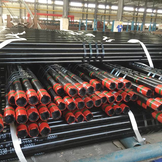 ZC production tubing with color-coded band markings at the pin ends and thread protectors fitted for shipment.
At a Glance — Common Production Tubing Sizes
API Specification 5CT, 11th Edition defines production tubing from 1.05" through 4.5" OD. Two sizes — 2⅜" and 2⅞" — cover the majority of onshore and shallow-water wells; 3½" carries high-rate and gas producers. The full table with wall, ID, and connection options is further down.
| OD | OD (mm) | Common weights (lb/ft) | Connection |
|---|---|---|---|
| 2⅜" | 60.32 | 4.60 / 5.80 / 7.35 | NU / EU |
| 2⅞" | 73.02 | 6.40 / 7.80 / 8.60 | NU / EU |
| 3½" | 88.90 | 9.20 / 12.70 | NU / EU |
Weight fixes the wall, and wall fixes the ID and pressure ratings — so a size is never complete without a weight. The full size and weight table with wall and ID is further down; for a quick dimensional check use the OD and weight size lookup →.
What we see on purchase orders: In OCTG purchase orders reviewed for Africa and Southeast Asia operators, drift diameter is the most frequently omitted specification item. When a PO reads "2-7/8 inch 6.40 lb/ft N80 EUE, Range 2" with no drift specification, the mill applies the default minimum from API 5CT — which may be smaller than the operator needs for the planned logging suite. We have seen completions where the perforation gun OD (53mm) would not pass through a 59.84mm nominal API drift — a 6mm gap that exists on paper but disappears when the gun is combined with a centralizer. The drift specification is not boilerplate: it defines the minimum usable bore for the entire well life.
What Is API 5CT Production Tubing?
Production tubing is a tubular string run inside the casing after the well is perforated, designed to convey formation fluids to the surface and to be pulled and replaced during the well's producing life — the production tubing primer covers the role in the completion in more depth. Unlike casing, which is cemented in place (see the casing sizes and weight tables for the outer strings), tubing sits inside the casing string and is set by a production packer positioned near the perforations. The annulus between the casing ID and tubing OD is used for annulus pressure monitoring, chemical injection, or gas lift.
The tubing string must withstand:
- Axial tension from self-weight and thermal expansion
- Internal pressure from reservoir and wellbore fluids
- External collapse pressure from the casing fluid column
- Corrosive environments: CO2, H2S, brine, and combined systems
Unlike casing, tubing is a consumable. Grades and weights are selected to last the well's economic life without requiring an unplanned workover for tubing replacement.
API 5CT Tubing OD Range and Weight Designations
API Specification 5CT defines tubing in ten nominal OD sizes from 1.05 inches to 4.5 inches. Each size is available in several wall thickness options, expressed as nominal weight in pounds per foot (lb/ft). Heavier weight means thicker wall, higher burst and collapse pressure ratings, and higher tensile capacity — at the cost of reduced bore ID and flow area.
The connection type — NU (non-upset), EU (external-upset), or IJ (integral joint) — affects the available OD at the connection and, for NU and EU types, the tensile efficiency of the joint relative to the pipe body.
For the complete burst, collapse, and tensile performance calculations by OD and weight, see the API 5CT specification tables →
To match tubing size and grade to well conditions, use the Pipe Grade Selector →
Tubing Size and Weight Table
The following table covers the primary commercial sizes from API Specification 5CT, 11th Edition Table C.19. Dimensions are as defined in the standard.
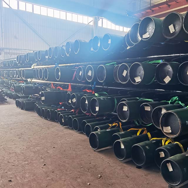 Finished OCTG in the ZC yard — green couplings and thread protectors fitted, each bundle carrying an identification tag.
| OD (in) | OD (mm) | Weight (lb/ft) | Connection | Wall (mm) | ID (mm) |
|---|---|---|---|---|---|
| 1.05 | 26.67 | 1.14 | NU | 2.87 | 20.93 |
| 1.05 | 26.67 | 1.48 | NU | 3.91 | 18.85 |
| 1.315 | 33.40 | 1.70 | NU / IJ | 3.38 | 26.64 |
| 1.66 | 42.16 | 2.30 | NU / EU / IJ | 3.56 | 35.04 |
| 1.9 | 48.26 | 2.75 | NU / EU | 3.68 | 40.90 |
| 1.9 | 48.26 | 3.65 | NU / EU | 5.08 | 38.10 |
| 2 3/8 | 60.32 | 4.60 | NU / EU | 4.83 | 50.66 |
| 2 3/8 | 60.32 | 5.80 | NU / EU | 6.45 | 47.42 |
| 2 3/8 | 60.32 | 7.35 | NU / EU | 8.53 | 43.26 |
| 2 7/8 | 73.02 | 6.40 | NU / EU | 5.51 | 62.00 |
| 2 7/8 | 73.02 | 7.80 | NU / EU | 7.01 | 59.00 |
| 2 7/8 | 73.02 | 8.60 | NU / EU | 7.82 | 57.78 |
| 3 1/2 | 88.90 | 9.20 | NU / EU | 6.45 | 76.00 |
| 3 1/2 | 88.90 | 12.70 | NU / EU | 9.52 | 69.86 |
| 4 | 101.60 | 9.50 | NU | 5.74 | 90.12 |
| 4 | 101.60 | 10.70 | NU / EU | 6.65 | 88.30 |
| 4 1/2 | 114.30 | 12.60 | NU / EU | 6.88 | 100.54 |
| 4 1/2 | 114.30 | 15.20 | NU | 8.56 | 97.18 |
Source: API Specification 5CT, 11th Edition, Table C.19. Weight values are nominal plain-end unless noted. Full table includes additional weight options per OD not shown here.
The two most commercially significant sizes are 2 3/8-inch and 2 7/8-inch, which together account for the majority of tubing orders in our supply chain. Within each OD, the weight choice is not a minor specification detail — it changes the ID, the flow area, and the pressure ratings by margins that directly affect well deliverability and completion integrity. Read the weight column together with the ID column, not in isolation.
Weight Selection for 2 7/8-Inch Tubing: Burst Comparison
The API 5CT tubing weight designations — 6.40 lb/ft and 8.60 lb/ft for 2-7/8 inch tubing — describe two very different engineering profiles despite appearing interchangeable in a parts list. The 8.60 lb/ft variant (7.82mm wall) has 42% higher burst rating and 27% higher collapse rating than the 6.40 lb/ft variant (5.51mm wall) — but its ID drops from 62.00mm to 57.78mm, cutting flow area by 14%. In gas wells where tubing velocity is the critical design parameter, the heavier-wall option that satisfies the pressure design may unacceptably restrict the flow rate. Weight selection is a simultaneous optimization of pressure containment, collapse resistance, tensile capacity, and flow area — not a single-axis decision.
The Barlow burst pressure formula (API 5C3 minimum wall basis) is:
P_burst = 0.875 × (2 × SMYS × t / OD)
Where 0.875 is the API minimum wall tolerance factor (87.5% of nominal wall), SMYS is the specified minimum yield strength in ksi, t is the nominal wall thickness in inches, and OD is the outside diameter in inches.
For 2-7/8 inch L80 Type 1 (SMYS = 552 MPa / 80 ksi), the calculation for the two most common weight options:
2-7/8" 6.40 lb/ft L80 (OD = 73.02 mm / 2.875 in, wall t = 5.51 mm / 0.217 in): P_burst = 0.875 × (2 × 80 × 0.217 / 2.875) = 0.875 × 12.08 = 10,570 psi (72.9 MPa)
2-7/8" 8.60 lb/ft L80 (OD = 73.02 mm / 2.875 in, wall t = 7.82 mm / 0.308 in): P_burst = 0.875 × (2 × 80 × 0.308 / 2.875) = 0.875 × 17.15 = 15,006 psi (103.5 MPa)
| Parameter | 6.40 lb/ft L80 | 8.60 lb/ft L80 | Change |
|---|---|---|---|
| Wall thickness | 5.51 mm (0.217 in) | 7.82 mm (0.308 in) | +42% |
| ID | 62.00 mm | 57.78 mm | −4.22 mm |
| Flow area | 3,019 mm² | 2,626 mm² | −13% |
| Burst rating (Barlow) | 10,570 psi (72.9 MPa) | 15,006 psi (103.5 MPa) | +42% |
| Collapse rating (relative) | Baseline | ~+27% | Higher |
The 42% burst improvement from 6.40 to 8.60 lb/ft is substantial — but the 13% reduction in flow area is not trivial in gas wells. A well producing at 5 MMscfd through 2-7/8" tubing sees a measurable increase in flowing tubing pressure if the heavier weight is selected without a corresponding velocity check. Run both the pressure design and the nodal analysis before committing to a weight.
Use the Barlow pressure calculator → to check ratings for your specific OD, wall, and grade.
Connection Types: NU, EU, and Integral Joint
Non-Upset (NU)
The pipe body OD continues through the pin end without enlargement. The coupling OD is larger than the pipe body. NU connections have lower tensile efficiency — approximately 80% of pipe body cross-sectional area — and are suitable for moderate-depth wells and lower tension loads. NU is the most economical connection option for shallow completions where tensile design is not the governing limit.
External-Upset (EU)
The pipe wall is thickened at the pin end by hot-working (upsetting) the tube ends before threading. This allows a fuller thread form and higher tensile efficiency approaching 100% of pipe body. EU is the standard connection for wells deeper than 2,000 m, deviated wells where bending loads add to tension, or any application where the tensile safety factor governs the design. EU is also preferred in wells where repeated workover running of the tubing string increases the cumulative fatigue at the connection.
Integral Joint (IJ)
The pin and box are machined directly into the pipe wall without a separate coupling. The OD at the joint is close to pipe body OD — typically pipe body OD plus a small thread engagement allowance. IJ availability is limited to specific OD and weight combinations (see the table above). IJ connections are used where coupling OD is a constraint, such as slim-hole completions or wells where the coupling must pass through a restriction.
For full connection performance data and running procedures, see the API 5CT tubing connections guide →.
Grade Selection by Well Conditions
The tubing grade is selected to meet the mechanical load requirements of the completion design and the corrosion resistance requirements of the reservoir environment. For the strength and application differences between the common OCTG grades, see the OCTG grades overview — N80, L80, P110, Q125.
| Well Environment | Recommended Grade | Key Selection Driver |
|---|---|---|
| Sweet, shallow (<2,000 m) | J55, N80-1 | Economy; low mechanical demand |
| Sweet, medium-depth | N80Q, L80 Type 1 | Higher tensile and burst capacity |
| Sour service (H2S present) | L80 Type 1, C90, T95 | NACE MR0175 / ISO 15156 hardness limit |
| HPHT (>150°C, >690 bar) | P110, Q125 | High yield strength for combined loads |
| CO2 corrosion environment | L80-13Cr, Super 13Cr | Chromium alloy for CO2 resistance |
| H2S + CO2 mixed environment | Super 13Cr or duplex CRA | Combined corrosion resistance required |
The maximum hardness limits for sour service grades are defined by API Specification 5CT, 11th Edition and enforced by NACE MR0175 / ISO 15156 to prevent sulfide stress cracking:
- L80 Type 1: 23 HRC maximum
- C90: 25.4 HRC maximum
- T95: 25.4 HRC maximum
For wells where CO2 partial pressure exceeds approximately 0.02 MPa (3 psi), sweet-service carbon steel grades such as J55 and N80 corrode at rates that typically require either inhibition or upgrade to a chromium-bearing grade. The threshold for selecting L80-13Cr over inhibited carbon steel depends on CO2 partial pressure, chloride concentration, temperature, and the economic comparison between chemical injection cost and the grade upgrade premium.
Named Tubing Selection Failure Modes
Understanding what goes wrong in tubing selection is more useful than understanding what the standard says in isolation. Three failure modes appear repeatedly in OCTG order reviews and completion post-mortems.
Failure Mode 1: Undersized Drift — Logging Tool Stuck in Tubing
Mechanism: When the drift diameter is not specified on the PO, or is specified at the API default without checking it against the planned downhole tool suite, the result is a well where the planned perforating gun, bridge plug, or logging tool cannot be run through the tubing. The tool is either too large to enter the tubing at surface, or enters the tubing but becomes stuck at a connection where the bore is slightly smaller than the pipe body bore due to coupling shoulder protrusion or scale buildup.
Diagnostic: Tool cannot be stabbed into the tubing at surface, or lands off-depth — tool weight indicator shows sudden resistance below a connection collar. Caliper log shows restriction at connection depth. Drift gauge at surface confirms tubing bore below the tool OD.
Fix: Before finalizing tubing size and weight, create a tool compatibility register: list every planned downhole tool (perforating gun, formation tester, logging tool, gas lift valve, coiled tubing OD) and its maximum OD. The tubing drift specification on the PO must exceed the maximum tool OD plus the operator's running clearance (typically ≥ 3mm radial, 6mm diametrical).
Failure Mode 2: Insufficient Burst Rating — L80 Replaced by J55 at Procurement
Mechanism: A completion is designed for 2-7/8 inch L80 tubing with a reservoir pressure of 8,500 psi (58.6 MPa). Procurement substitutes J55 — identical OD, weight, and connection — because J55 is in stock and L80 has a 6-week lead time. J55 6.40 lb/ft burst rating at minimum yield (55 ksi): P = 0.875 × (2 × 55 × 0.217 / 2.875) = 7,264 psi (50.1 MPa). The reservoir pressure of 8,500 psi exceeds the J55 burst rating by 17%. During a kill operation with bullheading, the tubing fails.
Diagnostic: Tubing rupture during high-pressure operation. Maximum surface treating pressure exceeded the design rating. Grade marking on the pipe body shows J55 (one green band) where L80 (one red + one brown band) was specified.
Fix: Never substitute a lower grade in tubing procurement without running the burst and collapse calculations for the substitute grade against the well design pressure. Verify grade by color code at goods receipt. In emergency procurement situations, run a de-rated well design based on the available grade before accepting the substitution.
Failure Mode 3: L80 vs L80 Type Substitution — Wrong Type Delivered
Mechanism: A PO specifying "L80 tubing" without the type designation receives L80-3Cr or L80-9Cr from a mill clearing stock. These grades are mechanically identical to L80 Type 1 but contain 3% or 9% chromium. In a sour-service well where H₂S is present, L80-3Cr and L80-9Cr do not have the same NACE MR0175 / ISO 15156 qualification basis as L80 Type 1 carbon steel — the chromium variants have different hydrogen permeation characteristics that require separate qualification testing. The mill's MTC reads "L80" — technically accurate but misleading.
Diagnostic: MTC lists "L80-3Cr" or "L80-9Cr" on the chemistry section while the grade line reads "L80." Well classified as sour service. Engineering review discovers the type substitution was not disclosed.
Fix: Always specify "L80 Type 1" — not "L80" — on every PO line for sour-service applications. This is explicitly addressed in API Specification 5CT, 11th Edition which distinguishes Type 1, 3Cr, 9Cr, and 13Cr as separate products. The three-character type designation on the PO is the only document control that prevents type substitution.
Drift Diameter and ID Considerations
API Specification 5CT, 11th Edition does not define a standard drift diameter for production tubing. The drift is specified by the purchaser on the PO to ensure that the minimum bore passes all planned downhole tools. Common practice is to specify a drift diameter at nominal ID minus 3.2 mm (⅛ inch), which clears most standard production logging and perforating tools.
For wells that will require coiled tubing intervention, the coiled tubing OD must be sized against the minimum tubing ID, accounting for any expected scale or paraffin buildup that reduces the effective bore over time. Wells planned for pump-and-flow operations must also confirm that the pump tubing string clearances are compatible with the tubing ID.
Specifying a drift diameter on the purchase order is not optional — it is the mechanism by which the buyer controls the minimum bore and verifies mill compliance before acceptance.
When NOT to Finalize Tubing Size Without Running All Four Checks
A tubing selection that satisfies three of these four design checks and fails the fourth creates a well with an unplanned workover built into its future. The most common failure is the drift check — it requires knowledge of the planned downhole tool program, which is often finalized after the tubing PO is placed. Reserve the drift specification on the PO as a hold item until the tool program is confirmed; do not default to the API minimum.
| Design check | What it catches | Consequence if skipped |
|---|---|---|
| Burst at max reservoir pressure | Grade and wall too thin for reservoir SITP | Tubing rupture during kill or pressure test |
| Collapse at max annulus pressure | Wall too thin for gas lift or annular pressure loss | Tubing collapse during gas lift cycling |
| Tensile at full string weight | Connection rating insufficient for well depth | Connection pull-out or string lost in hole |
| Drift vs tool OD | Bore too small for planned downhole tools | Tool stuck — workover required |
The table above is not a checklist to complete in sequence — all four checks are interdependent. Increasing wall thickness to satisfy burst also changes the collapse rating and reduces the flow area; changing connection type to satisfy tensile changes the coupling OD and may affect casing clearance. Size and weight selection is an iterative loop, not a linear process.
Purchase Order Guidance
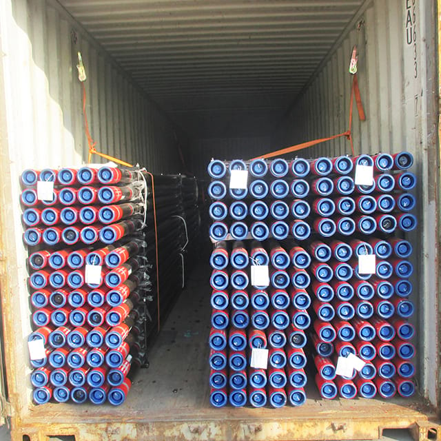 Tubing lashed and secured inside a shipping container for export to overseas operators.
Minimum required PO line items for production tubing:
- Grade and type designation: e.g., "L80 Type 1" not simply "L80"; "N80Q" not simply "N80"
- OD in inches, nominal weight in lb/ft, and connection type (NU or EU)
- Drift diameter in mm — hold this item open until the downhole tool program is confirmed
- Length range (R2, 8.5–10.0 m, is the standard for tubing)
- Heat treatment condition: Q+T for N80Q and all L80, C90, T95, P110
- Inspection level: PSL-1 or PSL-2
- MTC level: EN 10204 3.1 or 3.2
Wrong PO: "2-7/8 inch 6.40 lb/ft L80 EUE, API 5CT PSL-1, Range 2, 350 joints"
What the mill ships: L80-9Cr from stock (MTR reads "L80" without type designation). Drift diameter at API default (59.84mm). No PSL-2 inspection.
Correct PO: "2-7/8 inch 6.40 lb/ft L80 Type 1 per API Specification 5CT, 11th Edition, EUE (8-round, 8 TPI), PSL-2, Q+T heat treatment, per-pipe hardness ≤ 23.0 HRC recorded on MTC, drift diameter [specify mm — e.g. 57.50mm for coiled tubing compatibility], Range 2, EN 10204 3.2 MTC, 350 joints."
The difference between the wrong PO and the correct PO is approximately 40 words. Those 40 words determine whether the tubing that arrives is the tubing that was designed. The type designation, hardness limit, and drift specification are the three items most frequently missing from POs we review — and each omission creates a different compliance gap that the mill is not obligated to flag.
What to check on the MTR: Confirm the grade designation includes the type (L80 Type 1, not just L80). Confirm heat treatment is stated and matches the type requirement. Confirm the hardness test results are at or below 23.0 HRC for L80 Type 1. Confirm the drift diameter on the MTC matches the specified value on the PO — not the API default.
Frequently Asked Questions
What OD sizes are available for API 5CT production tubing?
API Specification 5CT, 11th Edition defines production tubing in OD sizes from 1.05 inches (26.67 mm) to 4.5 inches (114.3 mm), covering ten nominal OD designations: 1.05, 1.315, 1.66, 1.9, 2.063, 2 3/8, 2 7/8, 3 1/2, 4, and 4 1/2 inches.
What is the difference between NU and EU tubing connections?
NU (non-upset) tubing has the same OD at the pin end as the pipe body and uses an external coupling. EU (external-upset) tubing has an enlarged pin OD achieved by hot-working the tube ends, providing a larger thread contact area and thicker wall under the coupling. EU connections are stronger in tension and are preferred for deeper wells and higher-load completions.
What is the most common tubing size for oil and gas production wells?
The most widely used production tubing sizes are 2 3/8-inch (60.32 mm) and 2 7/8-inch (73.02 mm) OD, which cover the majority of onshore and shallow-water oil and gas wells. For higher-flow-rate wells and gas producers with large drawdowns, 3 1/2-inch (88.9 mm) tubing is common.
What grades of API 5CT are suitable for production tubing in sour service?
For H2S-containing environments meeting the sour service criteria of NACE MR0175 / ISO 15156, API 5CT tubing must be in a controlled-hardness grade: L80 Type 1 (max 23 HRC), C90 (max 25.4 HRC), T95 (max 25.4 HRC), or C110. The grade selection depends on H2S partial pressure, chloride concentration, and temperature as defined in ISO 15156-2.
Does the API 5CT specification define a drift diameter for tubing?
API Specification 5CT, 11th Edition does not define a fixed drift diameter for production tubing. The drift is specified on the purchase order by the buyer per API 5B requirements. Common practice is to specify a drift diameter sized to pass the production logging tools, perforating guns, or coiled tubing equipment planned for the well.
What is the difference between 2 7/8-inch tubing in 6.4 lb/ft and 8.6 lb/ft?
Both are 2 7/8-inch (73.02 mm) OD tubing with different wall thicknesses: 6.4 lb/ft has a 5.51 mm wall and 62.00 mm ID, while 8.6 lb/ft has a 7.82 mm wall and 57.78 mm ID. The heavier weight gives higher burst and collapse ratings and higher tensile strength, and is selected for deeper wells or higher reservoir pressures where the lighter weight does not meet load design.
Can API 5CT tubing be used interchangeably with API 5L line pipe?
No. API 5CT tubing and API 5L line pipe are produced to different standards with different chemical and mechanical requirements, dimensional tolerances, and inspection protocols. Substituting one for the other is not permitted by API specifications and may violate regulatory requirements in jurisdictions where pipeline design is governed by ASME B31.4 or B31.8.
What is an integral joint (IJ) tubing connection?
An integral joint tubing connection has the pin and box machined directly into the pipe wall without a separate coupling. The box is machined into one end of the pipe and the pin into the other, reducing the connection OD to near pipe body OD. Integral joints are useful in slim-hole completions or where coupling OD would create a restriction, and are available only in select OD and weight combinations per API 5CT.