

Reducer couplings and reducing couplings are among the most commonly specified fittings in oil and gas, petrochemical, and process piping — yet the terminology causes persistent confusion. Both terms refer to a pipe fitting that transitions between two different pipe sizes. The real engineering choices are about fitting type (buttweld reducer vs threaded reducing coupling), geometry (concentric vs eccentric), and material grade. Selecting incorrectly between concentric and eccentric reducers, or omitting the orientation from a purchase order, can cause pumping problems, pigging failures, and rework on completed spools.
ZC Steel Pipe supplies carbon steel buttweld reducers to ASME B16.9 in ASTM A234 WPB and alloy grades, covering NPS ½ through 48 across all standard schedules. Supply covers EPC projects in Africa, the Middle East, South America, and Southeast Asia, with EN 10204 3.1 mill test certificates and third-party inspection on request.
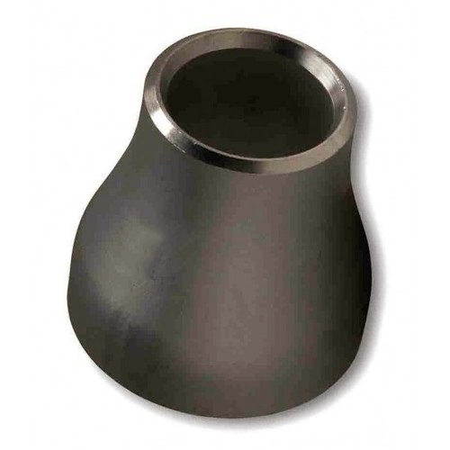 Carbon-steel concentric butt-weld reducer — both pipe ends on a common centreline.
Quick Answer
"Reducer coupling" and "reducing coupling" are the same thing — a fitting that joins two pipe sizes. The engineering decisions are fitting type, geometry, and grade:
| Question | Answer |
|---|---|
| Reducer coupling vs reducing coupling | Interchangeable terms — both mean a pipe-size reduction fitting |
| Buttweld reducer standard | ASME B16.9, NPS ½ to 48 (concentric and eccentric) |
| Socket-weld / threaded coupling standard | ASME B16.11, NPS ⅛ to 4 |
| Concentric reducer | Vertical runs and horizontal gas lines — both centrelines aligned |
| Eccentric reducer | Horizontal liquid lines — bottom flat (BF) for drainage and pigging, top flat (TF) at pump suction |
| Default carbon-steel grade | ASTM A234 WPB |
The two decisions that most often cause rework: choosing concentric where an eccentric is required in horizontal liquid service, and omitting the BF/TF orientation from the purchase order line item.
What we see on orders: On a Middle East crude oil pump station project, the pump suction spool for a 1,800 m³/h centrifugal pump contained a 16 × 12 horizontal reducer. The spool drawing said "eccentric reducer" but the purchase order line item said only "eccentric reducer, 16 × 12, A234 WPB, ASME B16.9" — no orientation stated. The fabricator installed a top-flat eccentric reducer, reasoning that the top being flat would look neater and match the isometric more cleanly. In pump suction service, top-flat orientation creates a high point where gas accumulates above the liquid surface at the pump inlet, causing cavitation at flows above 55% rated capacity. The pump was never able to reach design throughput. Cutting out and replacing the reducer with a correct bottom-flat unit — to keep the pipe invert consistent — took 3 weeks at next planned maintenance. The fitting itself cost $430; the downtime, dismantling, and refabrication cost $18,000. Stating "BF" (bottom flat) or "TF" (top flat) on every eccentric reducer line item is a 3-character entry that eliminates this failure mode.
Terminology: Reducer Coupling vs Reducing Coupling
The terms reducer coupling, reducing coupling, and coupling reducer are used interchangeably throughout the piping industry and in supplier catalogues. They all refer to the same fitting function: connecting two pipes of different nominal sizes.
The ambiguity arises because "coupling" in some contexts refers specifically to a threaded or socket-weld sleeve fitting (a coupling is a straight connector), while in other contexts it is used loosely to describe any fitting that connects two elements. In oil and gas process piping, when engineers say "reducer coupling" they almost always mean a pipe size reduction fitting — not a mechanical shaft coupling or sleeve reducer used in rotating equipment, which is an entirely different product.
This article covers pipe size reduction fittings only.
Types of Pipe Size Reduction Fittings
Four fitting types accomplish a pipe size reduction in process piping, each governed by a different standard and suited to a different bore range and connection method.
Buttweld Reducers — ASME B16.9
Buttweld reducers are the standard fitting for NPS 2 and larger process piping. They are welded directly onto the pipe ends, producing a permanent joint of equal strength to the pipe. Two geometries are available:
Concentric reducer: Both pipe ends are on the same centreline. The diameter reduces symmetrically around the centreline axis.
Eccentric reducer: One side of the fitting is flat — either the bottom (bottom flat, BF) or the top (top flat, TF). The centreline shifts between the two ends.
Both types are covered by ASME B16.9 in sizes NPS ½ through 48 — the same dimensional standard that governs buttweld elbows and tees. The fitting is identified by its large-end NPS and small-end NPS: a 10 × 8 reducer has a 10-inch (254 mm) large end and an 8-inch (203 mm) small end.
Socket-Weld and Threaded Reducing Couplings — ASME B16.11
For small-bore piping (NPS ⅛ through 4), socket-weld and threaded reducing couplings provide a quicker and less skilled alternative to buttweld. The fitting has a larger socket or thread on one end and a smaller socket or thread on the other.
ASME B16.11 covers socket-weld and threaded fittings (elbows, tees, couplings, caps) in Classes 2000, 3000, and 6000 for socket-weld, and Classes 2000, 3000, and 6000 for threaded. The class designation sets the pressure rating.
Swage Nipples — MSS SP-95
A swage nipple is a short reducing fitting with plain or threaded male ends, used in threaded piping systems. It is concentric or eccentric and is covered by MSS SP-95 in sizes NPS ⅛ through 4 (and larger by agreement). The base material is typically ASTM A105 for carbon steel and ASTM A182 for stainless and alloy steel.
Reducing Elbows — ASME B16.9
A reducing elbow combines a direction change with a size change in a single fitting, with the large end at the inlet and the small end at the outlet. These are specialty fittings and are less common than standard elbows paired with separate reducers, but they reduce the fitting count in tightly constrained layouts.
Concentric vs Eccentric Reducers — Selection Guide
The choice between concentric and eccentric reducers is determined by the piping orientation and process service, not by pressure rating or cost.
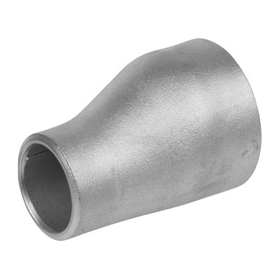 Eccentric butt-weld reducer — the flat side keeps the pipe invert or crown level across the reduction.
| Criterion | Concentric Reducer | Eccentric Reducer |
|---|---|---|
| Piping orientation | Vertical runs | Horizontal liquid lines |
| Centreline alignment | Maintained (both centrelines aligned) | Offset (one side flat) |
| Air pocket risk | Can trap air in horizontal liquid service | Prevents air pockets (BF orientation) |
| Pig passage | Not optimal for horizontal liquid | Preferred for horizontal piggable lines |
| Pump suction | Not used | Used (TF orientation keeps pipe top level) |
| Gas service (horizontal) | Preferred | Generally not required |
Bottom flat (BF): The bottom of the fitting remains level across the reduction. Standard choice for horizontal liquid lines.
Top flat (TF): The top of the fitting remains level. Used at pump suction nozzles to prevent air entrainment from a concentric or BF reduction above the pump inlet.
For a 20 × 16 inch horizontal crude oil line, specify an eccentric reducer, bottom flat, ASME B16.9. Specifying a concentric reducer at this location creates a low point where air accumulates, degrading pump performance and triggering cavitation.
For dimensional reference and wall thickness schedules, see the ASME B36.10M pipe schedule tables →
For pressure rating calculations at the reduced bore, use the Barlow Pressure Calculator →
A common misconception is that an eccentric reducer creates more pressure drop than a concentric reducer in horizontal liquid service. In practice, the pressure drop across the reducer fitting itself is almost identical for concentric and eccentric geometries of the same pipe-end sizes and included half-angle — both are in the range of 0.05–0.2 velocity heads depending on the reduction ratio and the included angle of the taper. The eccentricity shifts the centreline, not the flow path cross-section. The reason engineers sometimes observe higher pressure drop with eccentric reducers is that the downstream piping must include an additional elbow or offset to re-align the centreline — and it is the elbow, not the reducer, that contributes the bulk of the additional pressure drop. The reducer fitting itself is not the source of the penalty.
When NOT to Use Concentric Reducers
The concentric reducer is the default fitting in many project specifications, but five horizontal liquid service applications require an eccentric reducer. Using a concentric reducer in these situations creates a condition that cannot be corrected without cutting out and replacing the spool.
| Application | Correct type | Why concentric fails |
|---|---|---|
| Horizontal liquid piping (pump suction, gravity-flow lines) | Eccentric, bottom flat | Concentric creates a high-point air pocket on the centreline; causes cavitation or gas lock |
| Pump suction nozzle connection | Eccentric, top flat | Top flat keeps pipe top level, preventing air entrainment into pump impeller above the suction nozzle |
| Piggable pipelines (horizontal) | Eccentric, bottom flat | Concentric shifts centreline; eccentric maintains consistent pipe invert for pig travel |
| Horizontal slurry or viscous fluid lines | Eccentric, bottom flat | Solids settle at low points; concentric creates a low-centreline sump that concentrates solids |
| Liquid service where drainage on shutdown is required | Eccentric, bottom flat | Concentric creates a low point at the reduction that traps liquid on low-pressure side; eccentric drains freely |
The table above covers the cases where concentric geometry creates a structural flow problem, not just a preference. A concentric reducer in a pump suction horizontal line is not a marginal choice — it is an operating defect that will degrade pump performance until the fitting is replaced.
Standard Sizes
Buttweld reducers (ASME B16.9):
| Parameter | Range |
|---|---|
| Large end NPS | ½ to 48 |
| Large-to-small reduction | Typically one to three NPS sizes |
| Wall thickness | Matched to pipe schedule (STD, XS, Sch 40, 80, 160, XXS) |
| End preparation | Bevelled per ASME B16.25 for welding |
Large reductions (e.g. 24 × 12) are available but are non-standard and typically have longer lead times. For reductions greater than two standard pipe sizes, confirm dimensional availability with the supplier before locking the pipe schedule in the spool drawing.
Socket-weld and threaded reducing couplings (ASME B16.11):
| Parameter | Range |
|---|---|
| NPS | ⅛ to 4 |
| Pressure classes | 2000, 3000, 6000 lb |
| Connection | Socket weld or NPT thread |
Schedule Matching at Both Ends of a Reducer
The schedule designation on a reducer refers to the wall thickness at each pipe end. When the connected pipes run at different schedules, ordering a single schedule for both ends creates a weld joint mismatch that requires machining — a step that is routinely missed in spool fabrication reviews.
Example: 12 × 8 concentric reducer
A project orders a 12 × 8 buttweld reducer specified as "Sch 40" at both ends. The connected large-end pipe is NPS 12 Sch 20; the connected small-end pipe is NPS 8 Sch 80.
From ASME B36.10M:
- NPS 12 Sch 40: wall = 10.31 mm
- NPS 12 Sch 20: wall = 6.35 mm
Difference at the large-end weld joint: 10.31 − 6.35 = 3.96 mm step in ID. This step appears on the inside of the pipe at the weld root. ASME B31.3 Para. 328.4.3 requires that wall thickness changes at a weld joint be tapered at a slope of 1:3 or less, unless the step is within the ASME B16.9 OD tolerance. A 3.96 mm internal step at NPS 12 is outside tolerance and requires grinding or machining of the reducer bore before welding.
- NPS 8 Sch 40: wall = 8.18 mm
- NPS 8 Sch 80: wall = 12.70 mm
Difference at the small-end weld joint: 12.70 − 8.18 = 4.52 mm step in OD. The pipe wall (12.70 mm) is heavier than the reducer end (8.18 mm). This step appears on the outside of the joint and also requires machining — an external taper on the heavier pipe end — per ASME B31.3 transition requirements. A 4.52 mm step in an NPS 8 wall far exceeds the ASME B16.9 OD tolerance and cannot be accepted without machining.
Correct PO language: "12 × 8 concentric [or eccentric, BF] reducer, large end NPS 12 Sch 20 (6.35 mm min wall), small end NPS 8 Sch 80 (12.70 mm min wall). Wall schedule at each end to match connected pipe." The mill trims each end of the reducer to match the connected pipe schedule — this is a standard ASME B16.9 capability that must be stated explicitly on the PO.
To pull the exact wall thickness for the NPS and schedule at each reducer end, use the Pipe Size & Schedule Lookup →
Material Grades
Most process piping buttweld reducers are supplied in ASTM A234 WPB for general carbon steel service. The table below covers the main grades and their applications.
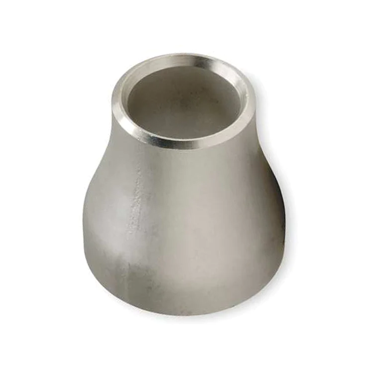 Stainless steel concentric butt-weld reducer for corrosive and CRA service.
| Standard | Grade | Service | Tensile Min | Yield Min |
|---|---|---|---|---|
| ASTM A234 | WPB | General, up to 482°C | 415 MPa (60 ksi) | 240 MPa (35 ksi) |
| ASTM A234 | WP11 | High-temp to 580°C | 415 MPa (60 ksi) | 205 MPa (30 ksi) |
| ASTM A234 | WP22 | High-temp to 600°C | 415 MPa (60 ksi) | 205 MPa (30 ksi) |
| ASTM A234 | WP91 | High-temp to 650°C | 585 MPa (85 ksi) | 415 MPa (60 ksi) |
| ASTM A420 | WPL6 | Low-temp to −46°C | 415 MPa (60 ksi) | 240 MPa (35 ksi) |
| ASTM A403 | WP316L | Stainless, corrosive | 485 MPa (70 ksi) | 170 MPa (25 ksi) |
| ASTM A815 | UNS S31803 | Duplex, sour service | 620 MPa (90 ksi) | 450 MPa (65 ksi) |
Source: ASTM A234, A420, A403, A815. Verify against current standard editions.
A234 WPB accounts for the majority of buttweld reducer orders in oil and gas carbon steel service. WP91 and WP22 reducers — used in high-temperature steam and reformer systems — carry significantly longer lead times and require heat treatment verification on the MTC; confirm availability before committing to the project schedule.
For a full grade selection guide covering carbon, alloy, and stainless materials, see the ASTM A234 WPB Fittings Grade Guide →
Reducer Fitting Failure Modes to Specify Against
Three failure modes recur across buttweld reducer installations. Each one is preventable at the procurement or design review stage.
Failure Mode 1 — Concentric reducer on pump suction horizontal line causing cavitation
Mechanism: A concentric reducer is installed on a horizontal liquid pump suction line reducing from NPS 10 to NPS 8. The top of the pipe centreline steps up 25.4 mm at the concentric reduction (half the OD difference). At this step-up, a gas pocket accumulates when any dissolved gas comes out of solution, or when flow drops during startup. The gas pocket is ingested into the pump impeller, causing intermittent cavitation damage visible as pitting on the impeller leading edges.
Diagnostic: Pump vibration data shows periodic cavitation signatures — elevated suction pressure fluctuations, impeller damage on inspection. A gas pocket is visible by acoustic monitoring or ultrasonic liquid level scan at the reducer location. Removing the pump inspection cover shows cavitation pitting on impeller leading edges.
Fix: Replace the concentric reducer with an eccentric reducer, bottom flat, in the next planned pump outage. Add the concentric-vs-eccentric orientation check to the P&ID mark-up review procedure and to the spool fabrication review checklist.
Failure Mode 2 — Schedule mismatch at weld joint creating stress concentration
Mechanism: A reducer is ordered as "Sch 40 both ends" for a line where the large-end pipe is Sch 80 and the small-end pipe is Sch 40. The reducer is fabricated with Sch 40 both ends. At the large-end weld joint, the pipe wall (12.70 mm for NPS 8 Sch 80) is 4.52 mm thicker than the reducer end (8.18 mm for NPS 8 Sch 40). ASME B31.3 requires a gradual taper; the abrupt step creates a stress concentration at the weld root. During hydrostatic test the joint passes, but in cyclic thermal service the step causes fatigue crack initiation at the weld root after 5,000 cycles.
Diagnostic: Fatigue crack is found at the large-end weld toe of the reducer during a scheduled RT survey. Cross-section confirms the crack origin at the internal step between the pipe wall (12.70 mm) and the reducer wall (8.18 mm).
Fix: Order reducers with each end schedule matched to the connected pipe schedule. State "large-end schedule NPS 8 Sch 80 / small-end schedule NPS 6 Sch 40" on the PO. Verify wall mismatch at all weld joints during isometric review before sending the spool for fabrication.
Failure Mode 3 — Swage nipple used in lieu of buttweld reducer in high-pressure service
Mechanism: A 3 × 2 reduction in a high-pressure instrument branch (15 MPa) is filled with a threaded swage nipple (MSS SP-95, carbon steel, threaded NPT). The system design required a socket-weld reducing coupling (ASME B16.11, Class 6000). The threaded nipple was a stock item and was used to avoid a 6-week lead time on the socket-weld coupling. Under sustained high-pressure service, the NPT thread flanks are loaded in shear. Over 14 months, the threaded joint loosens under thermal cycling and the joint leaks at the flange of the male thread.
Diagnostic: Leak at the 3 × 2 reduction joint, visible as staining or audible as a hiss. Inspection confirms a threaded connection, not socket-weld as required by the piping class specification.
Fix: Replace with the correct ASME B16.11 Class 6000 socket-weld reducing coupling as specified. Audit all instrument branch reductions on the system for the same substitution pattern.
Marking Requirements
Every ASME B16.9 reducer must carry the following markings on the fitting body:
- Manufacturer's name or trademark
- Material specification and grade (e.g. A234 WPB)
- Size (large-end NPS × small-end NPS)
- Schedule or wall thickness designation
- Heat number (for MTC traceability)
- The letter W if manufactured from welded tube
Verify all markings on receipt against the MTC. Missing heat number marking breaks the traceability chain and can trigger rejection by the third-party inspector.
Purchase Order Guidance
Minimum PO line items for buttweld reducers:
- Standard: ASME B16.9 (dimensional); ASTM A234 (material)
- Type: concentric or eccentric; if eccentric — specify BF (bottom flat) or TF (top flat)
- Size: large-end NPS × small-end NPS (e.g. 12 × 10)
- Schedule or minimum wall thickness — state large-end and small-end schedules separately if they differ
- Material grade: A234 WPB (default), WP11, WP22, WP91, or A420 WPL6 for low-temp
- End preparation: bevelled per ASME B16.25 (standard for buttweld)
- MTC: EN 10204 3.1 minimum
- NDE: MT or PT of fitting body if required by design code or project specification
- NACE MR0175 compliance if sour service
Flanged connections on the same spool are rated separately — for pressure-class selection, see the ASME B16.5 flange pressure-class guide →
Procurement Trap — Omitting Eccentric Orientation
Wrong PO: "Eccentric reducer, 8 × 6, A234 WPB, ASME B16.9." (No orientation specified.)
What ships: An eccentric reducer fabricated with top-flat orientation — the fabricator's default assumption in some shops. The spool drawing shows a plan view where the orientation is ambiguous. The fitting is dimensionally correct, correctly graded, correctly certified. It will pass dimensional inspection on receipt. The problem appears only when the spool is installed in a horizontal liquid line and the pump cannot reach rated flow.
Correct PO: "Eccentric reducer, 8 × 6, A234 WPB, ASME B16.9. Orientation: BOTTOM FLAT (BF) — pipe invert to remain at same elevation across reduction. Do not ship top-flat orientation unless explicitly specified for pump suction application." Confirm orientation on the isometric drawing and in the spool fabrication note.
Procurement Trap — Schedule Mismatch
A reducer ordered to Schedule 40 at both ends must be verified against the adjacent pipe schedule. If the large-end pipe is heavy wall (e.g. Schedule 80) and the small-end pipe is standard wall, a single-schedule reducer will not match the bevel geometry correctly, requiring machining on site — or, if the mismatch is missed, creating a stress concentration at the weld root that will only become visible during in-service cycling. Order reducers with the schedule of each end matched to the connected pipe — specify large-end schedule and small-end schedule separately if they differ.
Frequently Asked Questions
What is a reducer coupling?
A reducer coupling is a pipe fitting that connects two pipes of different nominal sizes, reducing the bore from a larger to a smaller diameter. In process and oil-and-gas piping, the term covers both buttweld reducers (concentric and eccentric) covered by ASME B16.9 for sizes NPS ½ through 48, and socket-weld or threaded reducing couplings covered by ASME B16.11 for sizes NPS ⅛ through 4. The terms reducer coupling and reducing coupling are used interchangeably in the industry.
What is the difference between a concentric and eccentric reducer?
A concentric reducer has both pipe ends on the same centreline, reducing the diameter symmetrically. It is used in vertical piping runs and in horizontal gas lines where centreline alignment is required. An eccentric reducer has one flat side, keeping the bottom of the pipe (bottom flat, BF) or the top of the pipe (top flat, TF) level. Eccentric reducers are used in horizontal liquid lines to prevent air pockets, to maintain a consistent pipe invert for drainage, and to facilitate intelligent pigging.
What standard covers buttweld reducers?
Concentric and eccentric buttweld reducers are covered by ASME B16.9 — Factory-Made Wrought Buttwelding Fittings — in sizes NPS ½ through 48. Short-run and non-standard reducing fittings may also be covered by ASME B16.11 (socket weld and threaded, NPS ⅛ through 4) or MSS SP-95 (swage nipples and bull plugs). Both the fitting type and the applicable dimensional standard must be stated in the purchase order.
What material grade is used for pipe reducers in oil and gas?
The most common material for carbon steel buttweld reducers in oil and gas service is ASTM A234 Grade WPB, which has a minimum tensile of 415 MPa (60,000 psi) and minimum yield of 240 MPa (35,000 psi). For low-temperature service below −29°C, ASTM A420 WPL6 (tested to −46°C) is required. For stainless steel service, ASTM A403 covers austenitic grades (TP304, TP316, TP316L), and ASTM A815 covers duplex and super duplex grades (2205, 2507).
When should I use an eccentric reducer instead of a concentric reducer?
Use an eccentric reducer (bottom flat orientation) in horizontal liquid piping to maintain a consistent pipe invert elevation for drainage, to prevent air pockets that would impair pump suction, and to allow pig passage through the reduction. Use a concentric reducer in vertical piping and in horizontal gas lines where the centreline symmetry is more important than invert alignment. Top flat eccentric reducers are used at pump suction nozzles to prevent air entrainment.
What is a swage nipple and how does it differ from a reducer?
A swage nipple (also called a swaged nipple) is a short reducing fitting with a male thread or plain end on both ends, used to reduce pipe size in small-bore threaded piping systems. It is covered by MSS SP-95 in sizes NPS ⅛ through 4 (and larger per agreement). Unlike a buttweld reducer (ASME B16.9), which is welded between two pipes, a swage nipple is threaded into couplings or fittings. Swage nipples are concentric or eccentric and are available in carbon steel (ASTM A105) and stainless steel (ASTM A182).
Can reducer fittings be used in sour service?
Yes. For NACE MR0175 / ISO 15156 sour service compliance, buttweld reducers in carbon steel must meet hardness limits (typically HRC ≤22 or HV10 ≤250 depending on the material and zone), and weld overlay or special heat treatment may be required. Specify NACE MR0175 compliance in the purchase order. For highly sour environments, duplex stainless steel (ASTM A815 Grade UNS S31803) or super duplex (UNS S32750) reducers are used to avoid sulfide stress cracking.
How is a reducer designated in a purchase order?
A buttweld reducer is designated by its large-end NPS, small-end NPS, and schedule or wall thickness — for example: 8 × 6 concentric reducer, Schedule 40, A234 WPB, ASME B16.9. An eccentric reducer also specifies the orientation: BF (bottom flat) or TF (top flat). Socket-weld reducing couplings are designated by NPS (large end × small end) and schedule, per ASME B16.11. Always confirm the end preparation (bevel per ASME B16.25 for buttweld) and surface treatment in the PO.
What does 'bottom flat' mean on an eccentric reducer?
Bottom flat (BF) means the flat side of the eccentric reducer is oriented downward, so the pipe invert (the lowest internal surface) remains at the same elevation across the reduction. This is the standard orientation for horizontal liquid lines because it prevents gas or air pockets from forming at the high point that a concentric reducer would create, and it maintains a consistent invert for pig travel and drainage. Top flat (TF) means the flat side is up and the pipe crown remains level — used at pump suction nozzles.
Why does omitting BF or TF on an eccentric reducer purchase order cause rework?
When orientation is not stated, the fabricator must assume one. Most fabricators default to bottom flat, but some interpret the isometric drawing differently — particularly where the plan view is ambiguous. If the installed orientation is wrong for the service (for example, a top-flat reducer installed in a horizontal pump suction line where bottom-flat was required), the spool must be cut out and replaced. The fitting itself may cost a few hundred dollars; the dismantling, fabrication, and downtime costs routinely exceed the fitting cost by a factor of 40 or more. Stating BF or TF is a 2-character entry on the PO line item that eliminates this failure mode entirely.