
Pipe flanges are among the most specified and most misspecified components in process piping. A flange rated for Class 150 at ambient temperature may be completely inadequate at 95°C with an injection pump downstream. A raised face flange that is correct for Class 300 steel piping can fracture a cast iron valve body during bolt-up. Getting the pressure class, material, and facing type right at the enquiry stage prevents field failures, re-procurement, and costly documentation audits.
ZC Steel Pipe supplies ASME B16.5 pipe flanges in carbon steel, alloy steel, and stainless grades across all six pressure classes, in sizes NPS ½ through 24, for process piping and pipeline projects in East Africa, the Middle East, and South America. This guide covers the pressure-temperature rating system, flange face types, material groups, and procurement requirements — including the class selection traps we see most often on purchase orders.
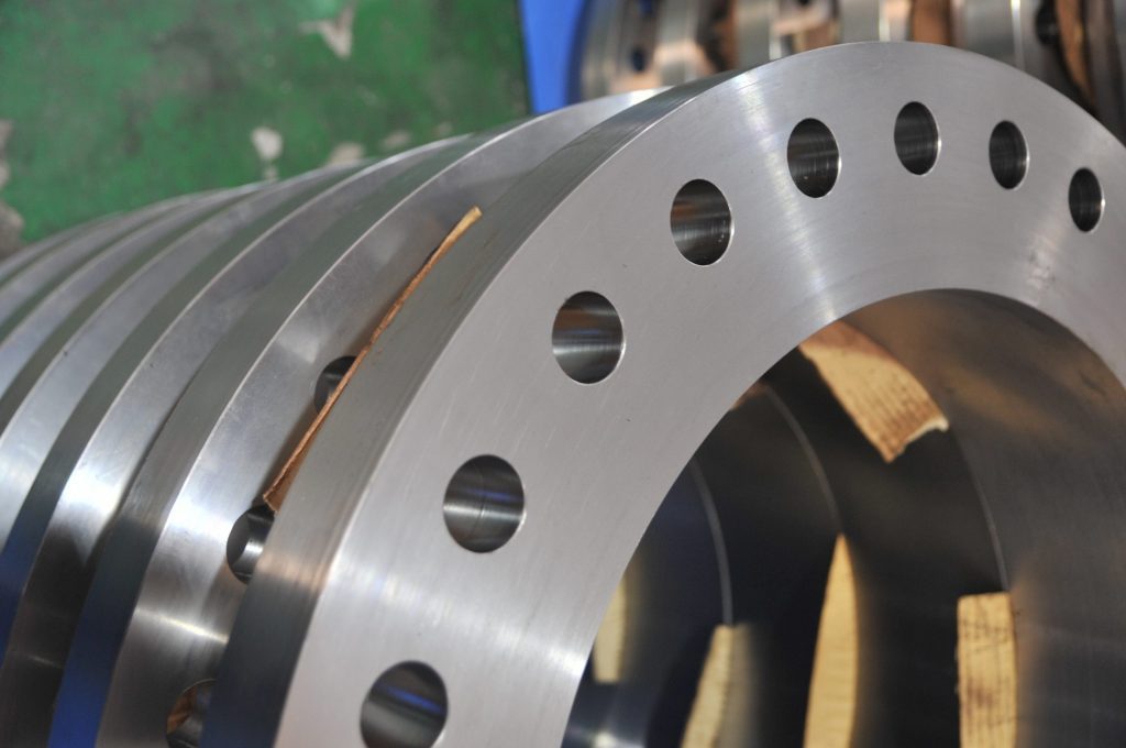 Stacked weld-neck and plate flanges with drilled bolt holes and machined sealing faces.
Quick Answer
ASME B16.5 covers pipe flanges NPS ½–24 in six pressure classes — 150, 300, 600, 900, 1500, and 2500. The class number is a designation, not a fixed pressure: a Class 150 carbon steel (A105) flange is rated 285 psi at ambient but only 260 psi at 93°C, so every selection must be checked against the pressure-temperature table for the actual material group and operating temperature. Weld neck flanges are the default for high-pressure, high-temperature, and cyclic service; slip-on flanges are limited to low-pressure, non-cyclic lines. Above NPS 24, ASME B16.47 applies instead.
| Class | A105 rating at ambient (psi) | A105 rating at 93°C (psi) |
|---|---|---|
| 150 | 285 | 260 |
| 300 | 740 | 680 |
| 600 | 1480 | 1360 |
| 900 | 2220 | 2040 |
| 1500 | 3705 | 3400 |
| 2500 | 6170 | 5665 |
What we see on orders: On an East Africa offshore chemical injection project, Class 150 raised face flanges were specified for a wellhead chemical injection line rated at "low flow rate and ambient pressure." The receiving engineer signed off without checking the operating conditions document, which showed the injection pressure at the wellhead flange (after the injection pump) as 24 bar (348 psi) at 95°C. At 93°C, the ASME B16.5 P-T rating for A105 Material Group 1.1 Class 150 is 260 psi (17.9 bar) — below the 24 bar operating pressure. The system passed the ambient-temperature hydrostatic test because the test pressure (37.5 bar) fell within the Class 150 ambient rating (285 psi / 19.6 bar × 1.5 hydrotest factor = 29.4 bar — test passed). Under sustained service at 95°C, gasket leaks developed at 3 of 8 flange pairs within 14 months. The correct specification was Class 300 (rated to 46.9 bar / 680 psi at 93°C). The Class 300 flange costs $65 more per flange than Class 150; the repair cost per leaked flange (dismantling, new gasket, re-assembly, re-test, documentation) exceeded $2,800.
1. Scope of ASME B16.5
ASME B16.5 — Pipe Flanges and Flanged Fittings — covers flanges and flanged fittings from NPS ½ through NPS 24 in pressure Classes 150, 300, 600, 900, 1500, and 2500. The standard specifies:
- Dimensions for each flange type and size
- Pressure-temperature (P-T) ratings by material group
- Materials permitted
- Bolt and gasket dimensions
- Marking requirements
For NPS 26–60, see ASME B16.47. For threaded pipe fittings and small flanges below NPS ½, see ASME B16.11. The B16.5 scope stops at NPS 24 — a point that matters when specifying large-bore pipeline tie-in flanges, where B16.47 Series A (formerly API 605) or Series B (formerly MSS SP-44) applies and the two series are dimensionally incompatible with each other and with B16.5.
2. Pressure Classes and P-T Ratings
The six pressure classes in B16.5 do not represent the allowable pressure at all temperatures — they are designations. Actual allowable pressure depends on material group and temperature. The following table shows P-T ratings for carbon steel Material Group 1.1 (ASTM A105):
| Class | −29 to 38°C (psi) | 93°C (psi) | 149°C (psi) | 204°C (psi) | 316°C (psi) |
|---|---|---|---|---|---|
| 150 | 285 | 260 | 230 | 200 | 140 |
| 300 | 740 | 680 | 655 | 600 | 510 |
| 600 | 1480 | 1360 | 1310 | 1200 | 1020 |
| 900 | 2220 | 2040 | 1965 | 1800 | 1530 |
| 1500 | 3705 | 3400 | 3270 | 3000 | 2550 |
| 2500 | 6170 | 5665 | 4565 | 4995 | 4250 |
The ratings in this table drop sharply as temperature rises. Class 150 loses 51% of its ambient rating by 316°C. Class 300 loses 31% by the same temperature — a narrower derating, which is why moderate-temperature elevated-pressure systems routinely require Class 300 even at pressures that would pass a Class 150 check at ambient. Always reference the current edition of ASME B16.5 Table 2 for the applicable material group and temperature before finalising any class selection.
The class number in ASME B16.5 is a designation, not a pressure rating. A Class 150 A105 flange is rated to 285 psi (19.6 bar) at ambient temperature — but only to 195 psi (13.4 bar) at 204°C (a 32% reduction) and 165 psi (11.4 bar) at 316°C (a 42% reduction). Engineers who look at the class number and assume it represents the maximum pressure at all temperatures will systematically under-specify flanges in moderate-temperature service. The ambient P-T rating is useful only for ambient-temperature systems. Every flange specification must be verified against ASME B16.5 Table 2 for the specific material group and the maximum operating temperature — not the ambient temperature unless that is genuinely the worst case.
P-T Rating Check: Class 150 vs Class 300
The following worked example uses the chemical injection project described above: process fluid at 95°C (approximately 203°F), maximum operating pressure 24 bar (348 psi), material A105 (Material Group 1.1).
Step 1 — Identify the applicable P-T table: ASME B16.5 Table 2-1.1 for Material Group 1.1 (A105).
Step 2 — Read the allowable pressure at 93°C (200°F, the closest table temperature):
| Class | Rating at 93°C (psi) | Rating at 93°C (bar) |
|---|---|---|
| 150 | 260 | 17.9 |
| 300 | 680 | 46.9 |
| 600 | 1360 | 93.8 |
Step 3 — Compare to operating pressure (348 psi / 24 bar):
| Class | Allowable at 93°C | Operating pressure | Result |
|---|---|---|---|
| 150 | 260 psi (17.9 bar) | 348 psi (24 bar) | FAILS — operating pressure exceeds rating by 34% |
| 300 | 680 psi (46.9 bar) | 348 psi (24 bar) | PASSES — margin 1.95× |
| 600 | 1360 psi (93.8 bar) | 348 psi (24 bar) | PASSES — margin 3.9× (over-specified) |
Step 4 — Selection: Class 300 is the minimum adequate class for this service. Class 600 is structurally adequate but unnecessarily expensive — the flanges, gaskets, studs, and bolt torque requirements all scale with class. Class 300 provides a 1.95× margin against operating pressure at the rated temperature, which is appropriate for a continuous-duty chemical injection line.
To convert between pressure ratings and pipe dimensions, use the Unit Converter →
3. Material Groups
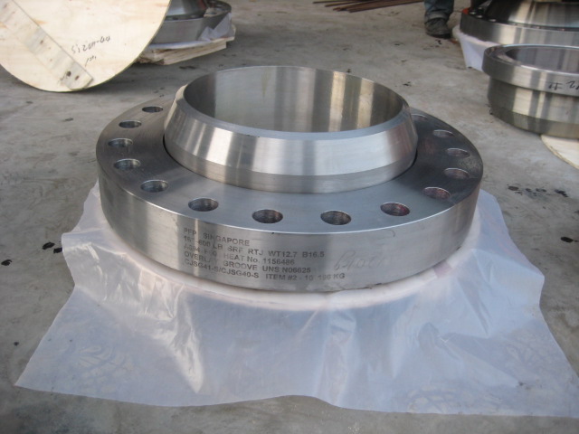 Weld-neck flange with painted stencil markings on the outer rim.
ASME B16.5 groups flange materials by allowable stress characteristics. Major groups relevant to oil and gas, pipeline, and process piping:
| Group | Typical Materials | Notes |
|---|---|---|
| 1.1 | A105, A515 Gr.70, A516 Gr.70 | Standard carbon steel, most common |
| 1.2 | A350 LF2 | Carbon steel, low-temperature impact tested |
| 1.7 | A182 F11, F22 | Chrome-moly alloy steel |
| 1.9 | A182 F91 | 9Cr-1Mo-V, high-temperature |
| 1.13 | A694 F52–F70 | High-yield pipeline service |
| 2.1 | A182 F304, F316 | Austenitic stainless |
| 2.2 | A182 F304L, F316L | Low-carbon austenitic stainless |
| 3.1 | A182 F51 (2205) | Duplex stainless |
Material Group 1.1 (A105) is the default for standard carbon steel process piping, covering the vast majority of flanges used in utility and moderate-service applications. Group 1.2 (A350 LF2) is required wherever Charpy V-notch low-temperature qualification is part of the design basis — a common requirement for subsea piping and arctic service. For pipeline flanges matching X65 or X70 pipe, specify A694 F65 or F70 (Group 1.13) — A105's 250 MPa minimum yield is insufficient for high-grade pipeline tie-in where the flange must match pipe body strength. The P-T ratings differ between material groups at elevated temperatures, so a Group 1.1 table does not apply to Group 1.9 flanges; use the table for the specific material purchased.
For the full dimensional range of pipe flanges by NPS and schedule, see the ASME B36.10M pipe schedule tables →
4. Flange Face Types
The seating face type must match between mating flanges and is specified in addition to pressure class. Mismatched facing types are a persistent source of gasket leaks and, in the case of raised face steel against flat face cast iron, flange cracking.
Raised Face (RF): The most common facing for Classes 150–2500. A raised circular ring on the flange face concentrates bolt load on the gasket. Spiral wound gaskets are standard for RF in Classes 300 and above. Flat sheet gaskets are used in Class 150 RF for low-pressure, non-critical service.
Flat Face (FF): The flange face is flush with the bolt circle face. Used when mating to cast iron or ductile iron equipment with flat face flanges — mixing a RF steel flange with a FF cast iron flange can fracture the cast iron by concentrating bolt load at the raised face perimeter. For flat face connections, use full-face gaskets that extend to the bolt circle. Not used for high-pressure service.
Ring Type Joint (RTJ): A machined groove in the flange face accepts a soft metal ring gasket (carbon steel, 316 SS, or soft iron). The ring deforms under bolt load to create a metal-to-metal seal. Standard for Class 600 and above in high-pressure, high-temperature, and sour gas service. RTJ flanges have an RTJ designation (e.g. Class 600 RTJ). RTJ requires a matched ring number (R, RX, or BX) — confirm the ring number matches the flange groove before assembly. RTJ is preferred for sour service because soft gaskets used in RF connections can be attacked by H2S environments.
Tongue and Groove (T&G) and Male and Female (M&F): Interlocking mating faces that fully confine the gasket. Used for special high-pressure services and pump nozzle connections. Less common than RF or RTJ, and not interchangeable in the field — both flanges in a mating pair must be of the same matching type (one tongue, one groove).
5. Flange Types
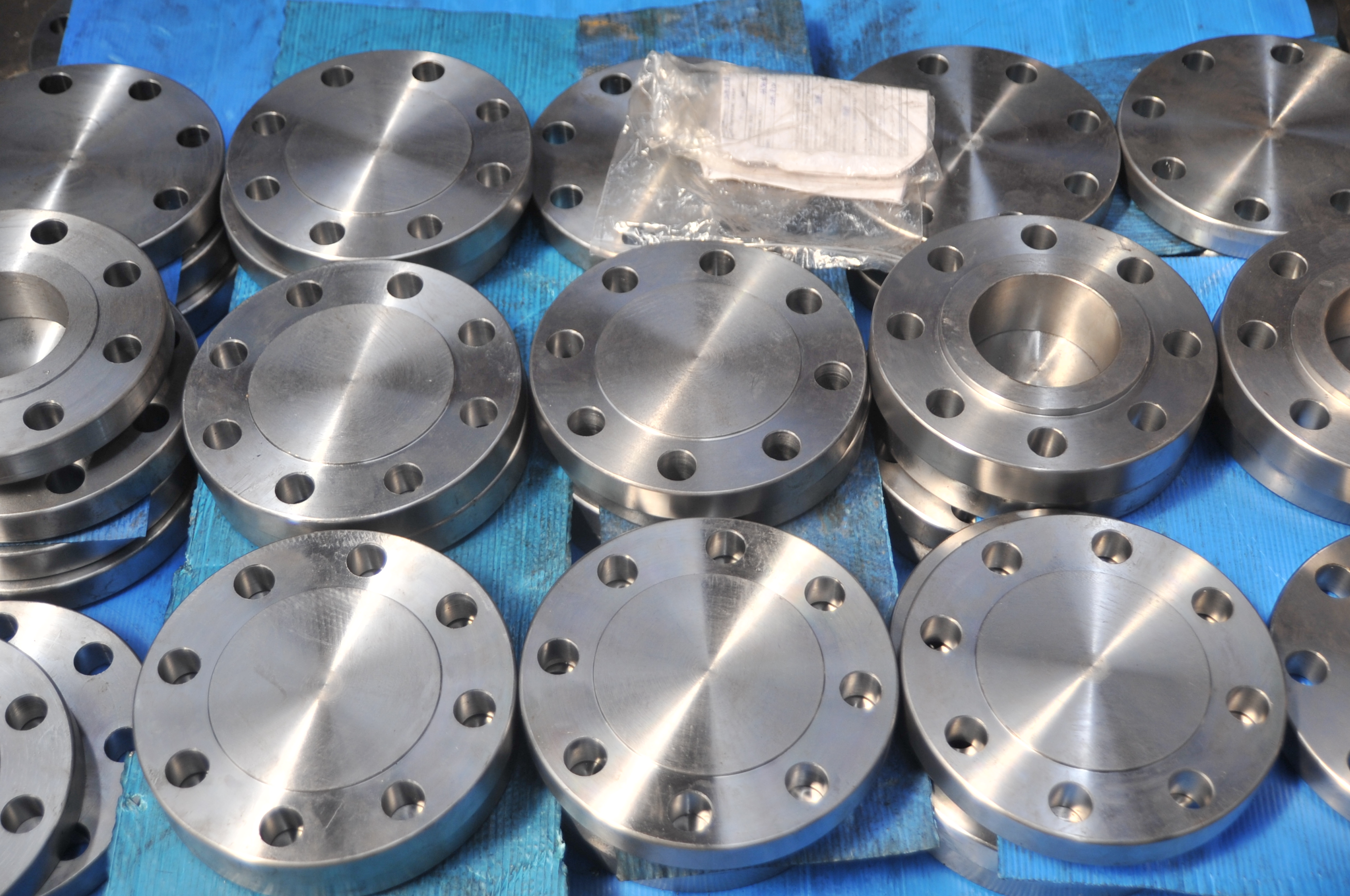 Assorted blind and weld-neck flanges laid out on a blue tarp.
| Type | Description | Best Application |
|---|---|---|
| Weld Neck (WN) | Long tapered hub, butt welded to pipe | High-pressure, high-temperature, fatigue service |
| Slip-On (SO) | Slides over pipe, fillet welded inside and outside | Low-pressure, non-cyclic, lower cost |
| Blind (BL) | Closes off end of pipe | Isolation, pressure testing |
| Socket Weld (SW) | Small bore (≤NPS 2), pipe inserted and fillet welded | High-pressure small bore piping |
| Threaded (TH) | Threaded bore, no welding | Non-critical small bore connections |
| Lap Joint (LJ) | Used with stub end, allows rotation for bolt hole alignment | Frequent dismantling, dissimilar material systems |
| Reducing | Pipe bore smaller than flange NPS | Transitions to smaller bore equipment |
Weld neck flanges have the best fatigue performance of any flange type and are mandatory in high-cyclic and HPHT service. The tapered hub distributes stress smoothly from flange to pipe, unlike the abrupt fillet weld geometry of a slip-on. Weld neck flanges and ASME B16.9 buttweld fittings share the same butt-weld end preparation, so a fabricated spool usually pairs both to the same schedule. Slip-on flanges may be restricted or prohibited by project specifications for pressure piping above Class 300, and for any piping with cyclic thermal loading — see Failure Mode 3 below for the mechanism.
6. Bolt and Gasket Requirements
Bolting: B16.5 specifies stud bolt diameters and lengths for each flange size and class. Standard bolt materials are ASTM A193 B7 (alloy steel stud bolts) with A194 2H heavy hex nuts. For stainless flanges, A193 B8M (316 SS) bolts with A194 8M nuts are typical. For sour service, bolt hardness must also comply with NACE MR0175 / ISO 15156 — A193 B7M (controlled hardness) with A194 2HM nuts is the standard sour-service bolting combination.
Gaskets for RF flanges:
- Class 150: flat ring gasket (ASME B16.21) or spiral wound
- Class 300–600: spiral wound gasket (ASME B16.20), typically 316 SS windings with graphite filler and inner/outer rings
- Class 900–2500: spiral wound with inner ring, or RTJ ring
Ring gaskets for RTJ flanges: Oval or octagonal soft iron or 316 SS rings per ASME B16.20. Ring hardness must be less than the flange groove hardness — if a harder ring is installed in a softer groove, the groove deforms and the flange face is damaged, requiring re-machining or replacement. Verify ring hardness against flange material hardness before assembly, particularly when using 316 SS rings against carbon steel flanges (the SS ring is harder and should only be used in SS flanges or Alloy 625 flanges).
7. Pipeline Flanges — ASTM A694
Pipeline tie-in flanges for high-grade API 5L pipe require A694 material where A105 yield strength (250 MPa minimum) is insufficient. The A694 grade must match the minimum yield of the pipe to ensure the flange is not the weak point in the system:
| A694 Grade | Min Yield (MPa) | Matching API 5L Grade |
|---|---|---|
| F42 | 290 | X42 |
| F52 | 360 | X52 |
| F60 | 415 | X60 |
| F65 | 450 | X65 |
| F70 | 485 | X70 |
The flange grade has to track whatever line pipe the project runs — see our guides on seamless vs welded line pipe selection and ERW, LSAW, and SSAW welded pipe types for how pipe grade and manufacture are fixed before the flange is ordered.
A694 flanges must also be supplemented with Charpy V-notch impact testing and PSL2-equivalent mill certification when matching PSL2 pipe. The Charpy requirement for the flange should match the pipe's Charpy acceptance criterion at the test temperature — this is sometimes omitted from the flange PO when the pipe PO was written separately. We see this gap on pipeline spool fabrication orders where the pipe and flanges are purchased from different suppliers: the pipe carries its Charpy record, but the flange MTC is silent on impact testing. Resolve this at the procurement stage, not during spool fabrication inspection.
When NOT to Use Class 150
Class 150 is appropriate for ambient-temperature, low-pressure utility service. It is the wrong choice in a wider range of process conditions than is commonly assumed. Use the following table as a minimum check before specifying Class 150:
| Service condition | Minimum class | Why Class 150 fails |
|---|---|---|
| Operating pressure > 17.9 bar at temperatures above 93°C | Class 300 | Class 150 A105 rating at 93°C = 260 psi (17.9 bar) — insufficient for most elevated-temperature process services |
| Process piping above 204°C | Class 300 or 600 | At 204°C, Class 150 rating is 200 psi (13.8 bar); most process systems operate above this at elevated temperature |
| Sour gas or H2S-containing service | Class 300 minimum with RTJ facing | Class 150 RF with soft gaskets not acceptable for sour containment; RTJ requires Class 600+ machined groove flanges |
| Cyclic thermal service (>2 startups/shutdowns per year) | Weld neck Class 300+ | Class 150 with slip-on flanges has the lowest fatigue rating of any flange combination; not suitable for cyclic loading |
| Connection to ASME Class 300 or higher equipment nozzle | Match equipment class | Direct-mating Class 150 to Class 300 is not permitted; reducers must use blind flanges or rated transition |
| Pipeline ASME B16.47 NPS 26+ | ASME B16.47 Series A or B | Class 150 in B16.5 covers NPS ½–24 only; large flanges require B16.47 and are not Class 150 B16.5 |
The two conditions most frequently missed in project engineering are the temperature derating above 93°C and the cyclic loading prohibition on slip-on flanges. Both appear in the ASME B16.5 tables, but neither is obvious from the class designation alone.
Procurement Trap — Wrong Class for Operating Temperature
A procurement team specifying flanges for an elevated-temperature service needs to verify the P-T table, not just the class number. The following example shows how the wrong PO reaches the correct specification — and why the system still fails.
Wrong PO: "ASME B16.5 Class 150 RF flange, NPS 2, ASTM A105."
What ships: An A105 Class 150 raised face flange, correctly certified to ASME B16.5. Rated 285 psi at ambient; only 260 psi at 93°C. The 24 bar (348 psi) system pressure at 95°C operating temperature exceeds this rating. The mill is fully compliant — the error is in the specification.
Correct PO: "ASME B16.5 Class 300 RF flange, NPS 2, ASTM A105. Design pressure 24 bar (348 psi) at 95°C — class confirmed against B16.5 Table 2-1.1 P-T rating for Material Group 1.1 at 93°C (680 psi — adequate). State operating pressure and temperature on PO; do not specify class without verifying the applicable P-T table."
Including the operating pressure and temperature on the PO creates a documented record that the class was selected against the P-T table for the actual service conditions — not assumed from the class number at ambient. This record is the minimum required for piping design documentation under most project quality management systems.
Pipe Flange Failure Modes to Specify Against
Failure Mode 1 — Class 150 Gasket Leakage Above the Temperature-Derated P-T Limit
Mechanism: Class 150 A105 flanges are installed in a chemical injection line that routinely operates at 95°C and 22 bar. The Class 150 P-T rating at 93°C is 17.9 bar — the system is at 22 bar, which is 23% above the rating. Under sustained service above the P-T limit, the bolt load required to maintain gasket seating stress is insufficient to overcome the hydrostatic end-force at the elevated pressure and temperature combination. The gasket loses seating stress and leaks — typically at the weakest gasket in the joint, usually a slightly misaligned one from reassembly.
Diagnostic: Leakage concentrated at or adjacent to the gasket OD, not at the bolt holes or flange face. This is classic gasket blowout, not flange face damage. Flange face inspection after disassembly shows no damage; the gasket shows an irregular blowout track. Review of the P-T table confirms the system was operated above the Class 150 rating at the service temperature.
Fix: Upgrade to Class 300 or higher for all flanges in service above the Class 150 P-T rating. Document the design basis P-T check in the flange specification sheet and retain it as part of the piping design record.
Failure Mode 2 — Raised Face Flange Mated Against Flat Face Cast Iron Equipment
Mechanism: An A105 Class 150 raised face (RF) flange is bolted to a cast iron valve with a flat face (FF) design. The raised face concentrates bolt load on the raised ring area of the steel flange, creating a bending moment at the valve body flange as the bolt load is applied. Cast iron flanges have low bending strength — tensile strength typically 170 MPa versus 485 MPa for A105. The cast iron flange cracks at the raised face perimeter contact line when the bolts are torqued to the RF seating stress, even though the bolt torque itself is within the standard value for the steel flange.
Diagnostic: A crack is visible at the gasket OD on the cast iron flange, running circumferentially. The crack appears during bolt-up — immediately or within the first startup thermal cycle. The steel RF flange face is undamaged. The failure is due to material incompatibility between RF steel and FF cast iron, not overtorquing.
Fix: When mating to cast iron or ductile iron equipment, specify flat face (FF) steel flanges to ASME B16.5, with full-face (FF) gaskets that extend to the bolt circle. Never use RF steel flanges against any cast iron flange face. Add a check to the piping material specification: "RF flanges not permitted in connections to cast iron or ductile iron equipment — specify FF."
Failure Mode 3 — Slip-On Flange Weld Root Failure Under Cyclic Thermal Service
Mechanism: Class 150 slip-on flanges (fillet-welded inside and outside the pipe bore) are used in a steam condensate return line with 2 daily startup/shutdown cycles. The slip-on flange is attached by two fillet welds — one at the pipe ID and one at the pipe OD face. Under thermal cycling, the fillet weld at the ID root is exposed to full thermal stress (the temperature differential between pipe and flange body) without the smooth stress transition of a weld neck tapered hub. After approximately 3,000 thermal cycles (4 years of daily operation), a fatigue crack initiates at the ID fillet weld root and propagates through the weld into the pipe wall.
Diagnostic: Leak at the pipe-to-flange joint, not at the gasket face. Visual inspection shows a crack at the ID weld root, visible after flange removal. The crack is oriented circumferentially at the weld toe. Fatigue striations are visible on the fracture surface under low-magnification examination.
Fix: For any piping with more than 2 thermal cycles per year, specify weld neck flanges instead of slip-on. For steam, hot oil, or cyclic heat exchanger piping, weld neck flanges are mandatory in most project specifications. Add the thermal cycle count to the flange type selection criteria in the piping engineering specification.
8. Procurement Checklist
Before finalising a flange purchase order, verify all of the following. Missing any item is the source of the procurement traps described above:
- Standard: ASME B16.5 (latest edition), or ASME B16.47 for NPS >24
- Flange type: WN / SO / BL / SW / TH / LJ
- Pressure class: 150 / 300 / 600 / 900 / 1500 / 2500 — confirmed against P-T table for material group and operating temperature
- NPS
- Bore: to match pipe schedule or as specified
- Facing: RF / FF / RTJ (and ring number for RTJ)
- Material: A105, A350 LF2, A182 F304/316/316L, A694 F52–F70, etc.
- NACE MR0175 / ISO 15156: specify for sour service (requires hardness limits and material restrictions)
- Bolting: A193 B7 + A194 2H (standard carbon steel); A193 B7M + A194 2HM (sour service); specify if SS or special alloy required
- Mill test certificates: EN 10204 3.1 minimum; specify 3.2 for critical service
- Operating pressure and temperature: state on PO as the basis for class selection
For pressure calculations and pipe dimension checks, use the Barlow Pressure Calculator → and the Unit Converter →
Frequently Asked Questions
What pressure classes are covered by ASME B16.5?
ASME B16.5 covers six pressure classes: 150, 300, 600, 900, 1500, and 2500. The class number reflects the approximate pressure rating in psi at 100°F for the baseline material group. For example, Class 150 carbon steel (Material Group 1.1) is rated at 285 psi at 100°F, while Class 2500 is rated at 6170 psi at 100°F. Actual allowable pressure decreases with increasing temperature — always check the appropriate pressure-temperature table for the specific material group.
What is the difference between weld neck and slip-on flanges?
A weld neck flange has a long tapered hub that is butt welded to the pipe — the taper provides a smooth transition of stress and makes the joint ideal for high-pressure, high-temperature, cyclic, and fatigue-sensitive service. A slip-on flange slides over the pipe and is fillet welded on both the inside and outside face — it is easier to align in the field and costs less, but has a lower fatigue rating than a weld neck. Weld neck flanges are the preferred choice for critical service; slip-on flanges are used for low-pressure, non-cyclic applications.
What is the pressure rating of a Class 150 flange in carbon steel?
For carbon steel Material Group 1.1 (ASTM A105), the Class 150 flange pressure-temperature ratings per ASME B16.5 are: 285 psi at −29°C to 38°C, 260 psi at 93°C, 230 psi at 149°C, 200 psi at 204°C, 170 psi at 260°C, 140 psi at 316°C, 110 psi at 371°C, and 80 psi at 399°C. The rating decreases significantly with temperature, so Class 150 flanges should not be assumed to hold their ambient pressure rating at elevated temperatures.
What facing type should I specify for high-pressure service?
For high-pressure service (Class 600 and above), Ring Type Joint (RTJ) facing is the standard choice. RTJ uses a soft metal ring gasket (oval or octagonal cross-section) seated in matching grooves on both flange faces, which deforms under bolt load to create a metal-to-metal seal. Raised Face (RF) with spiral wound gaskets is used in Classes 300–900 and is acceptable in many high-pressure applications. RTJ is preferred where frequent make-up and break-out is required, or for HPHT wellhead service.
What material is ASTM A105?
ASTM A105 is the most common material for carbon steel pipe flanges. It covers carbon steel forgings for ambient and higher-temperature piping. Chemistry: C ≤0.35%, Mn 0.60–1.05%, P ≤0.035%, S ≤0.040%, Si 0.10–0.35%. Mechanical properties: minimum tensile 70,000 psi (485 MPa), minimum yield 36,000 psi (250 MPa), minimum elongation 22%. A105 flanges are supplied in the normalised or quenched and tempered condition and are used from −29°C to 427°C in standard service.
What is ASTM A694 flange material used for?
ASTM A694 covers carbon and alloy steel forgings for high-yield-strength flanges intended for use in pipeline service. Grades are designated by yield strength in ksi: F42, F46, F52, F56, F60, F65, F70. An A694 F65 flange has a minimum yield strength of 65,000 psi (450 MPa), matching API 5L X65 pipe — ensuring the flange yield strength is not the weak link in a high-pressure pipeline tie-in. A694 flanges are mandatory for high-pressure, high-grade pipeline projects where A105 yield strength is inadequate.
What NPS range does ASME B16.5 cover?
ASME B16.5 covers NPS ½ through NPS 24 (DN 15 through DN 600). For larger diameters NPS 26 through NPS 60, ASME B16.47 Series A (formerly API 605) and Series B (formerly MSS SP-44) apply. The two B16.47 series have different dimensional standards and are not interchangeable — confirm which series is required by the project specification before ordering large-diameter flanges.
Can you bolt a Class 150 raised face flange directly to a cast iron valve?
No — a raised face (RF) steel flange must not be bolted directly to a cast iron flat face (FF) flange. The RF ring concentrates bolt load on a small contact area and creates a bending moment at the cast iron body that can crack it during bolt-up, even at normal torque values. When connecting to cast iron or ductile iron equipment, specify flat face (FF) steel flanges with full-face gaskets extending to the bolt circle. This is one of the most common flange incompatibility errors in piping-to-equipment connections.
Do I need to specify NACE MR0175 for flanges in sour service?
Yes — flanges in H2S-containing service must comply with NACE MR0175 / ISO 15156, which imposes hardness limits and material restrictions. For carbon steel (A105), the standard limits maximum hardness to 22 HRC (or 250 HBW) for sour service. The PO must explicitly state 'NACE MR0175 / ISO 15156 compliant' and request hardness certification on the MTC. Standard A105 flanges may exceed this hardness limit — do not assume a standard A105 flange is automatically sour-service qualified.