
The most vulnerable point on any buried or subsea pipeline is not the factory-coated pipe body — it is the girth weld zone where that factory coating ends. Every metre of pipeline contains at least two of these zones, and the corrosion protection system applied there in the field must perform for the same design life as the mainline coating around it. A poorly specified or poorly executed field joint coating can render an otherwise well-engineered pipeline coating system ineffective within a few years of commissioning. Selecting the right field joint coating system — and specifying it correctly on the purchase order — is therefore one of the highest-leverage decisions an EPC coating engineer makes.
ZC Steel Pipe supplies coated line pipe with factory-applied 3LPE, FBE, and concrete weight coating systems to EPC contractors and pipeline operators in Africa, the Middle East, South America, and Southeast Asia, with EN 10204 3.1 material test certificates and full documentation to support field joint coating system selection.
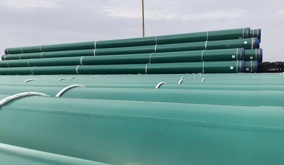 Green FBE-coated LSAW line pipe with capped ends in the yard — ZC supplied this X65M FBE LSAW pipe for a project in Nigeria. The bare cutback at each end is where the field joint coating will later be applied.
At a Glance — Which Field Joint System
| Mainline coating & service | Field joint system | Why |
|---|---|---|
| 3LPE / 3LPP / FBE onshore, ≤80°C | Three-layer heat shrink sleeve (HSS) | Mirrors the mainline structure; ~15–20 min per joint; low skill dependence |
| Operating temperature 80–150°C | Liquid epoxy (ISO 21809-3 Type A) | HSS adhesive softens above its rating; epoxy holds to 150°C |
| Irregular geometry (tees, bends) or subsea beyond ~200 m | Liquid epoxy or polyurethane | HSS cannot conform, and is unqualified for deep hydrostatic pressure without project testing |
| Mainline includes CWC or foam insulation | Anti-corrosion FJC + poured infill | Only a structural infill restores the concrete / insulation OD profile |
The single most common in-service failure is a temperature-rating mismatch — an HSS grade rated below the mainline coating. Match the FJC temperature rating to the mainline coating rating, not the pipe grade. For the concrete-profile case see the concrete weight coating field joint requirements →, and for the mainline layer these joints must equal, see the 3LPE / FBE / 3LPP coating selection guide →.
What we see on orders: On a 120-km buried gas pipeline in Sub-Saharan Africa, the FJC contractor selected a standard-grade heat shrink sleeve rated to 60°C — the most common stock grade available locally. The mainline 3LPE coating was rated to 80°C, and the pipeline operating temperature at the compressor outlet section reached 72°C during peak summer operation. HSS adhesive at those joints softened, sleeves began disbonding within 18 months, and 15% of joints on the hot section required excavation and re-coating. The FJC system temperature rating must match the mainline coating temperature rating — not just the pipe grade temperature. This information must be transferred from the pipe coating mill to the FJC contractor in writing before mobilisation.
What Is a Field Joint?
When a steel pipe is factory-coated — whether with a three-layer polyethylene (3LPE) system, a three-layer polypropylene (3LPP) system, or a fusion-bonded epoxy (FBE) system — both pipe ends are intentionally left bare over a distance known as the cutback zone. This uncoated length is typically 100–150 mm from each pipe end, though the exact dimension is determined by the welding procedure specification and may be greater on large-diameter pipe where preheat needs to extend further from the weld. The bare steel in the cutback zone is protected only by a temporary primer or rust-inhibiting compound during storage and transport.
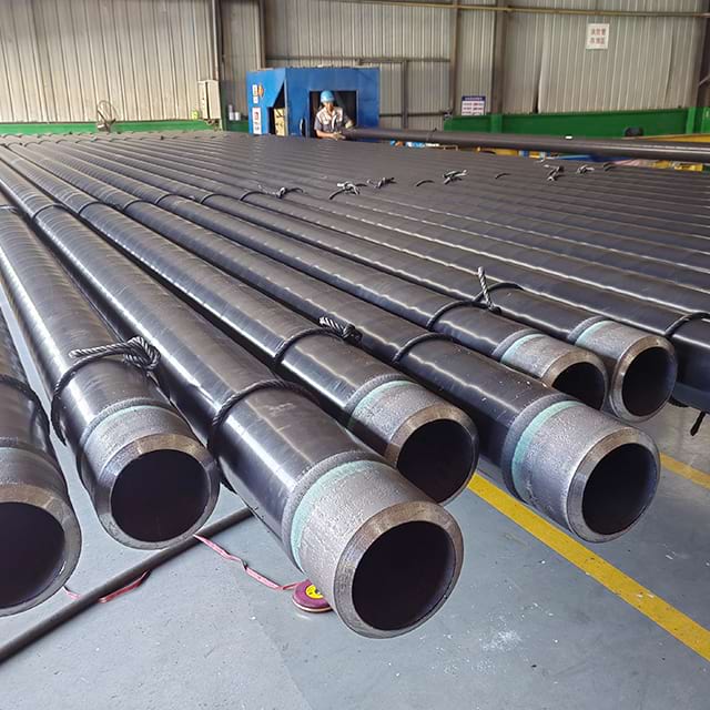 Coated line pipe with bevelled ends ready for girth welding — the bevel and the uncoated cutback zone at each end are prepared for field welding and the field joint coating that follows.
In the field, lengths of coated pipe are welded end to end into a continuous string. After each girth weld is completed and accepted by non-destructive testing (NDT), the bare steel between the two adjacent factory coating ends must be coated before the pipe is lowered into the trench or laid on the seabed. The system used to coat this zone is the field joint coating (FJC).
The FJC zone is the most vulnerable section of the pipeline coating system for several compounding reasons. The steel surface has been heat-affected by welding, which changes the surface profile and may introduce oxide layers that reduce coating adhesion. The work is performed in open-air field conditions — in direct sunlight, in rain, or at sub-zero temperatures on Arctic projects — rather than in a controlled factory environment. Application quality depends heavily on the skill of the field crew. And the FJC must bond not only to the bare steel but also to the tapered or cut edges of the adjacent factory coating, creating a transition zone where the risk of disbondment is highest. For all of these reasons, the FJC system must be specified to meet or exceed the corrosion protection performance of the mainline coating it bridges.
A holiday on the factory-coated pipe body is one failure point in one location. A holiday on a field joint coating is a failure point compounded by proximity: the girth weld heat-affected zone — where hydrogen cracking risk and microstructural changes from welding are concentrated — is located within centimetres of the field joint coating edge. A corrosion pit initiated at a field joint holiday will propagate into the HAZ before it grows into the adjacent parent pipe body. Field joints are not simply the gap between pipe end coatings — they are the highest-consequence coating zone per linear metre of the entire pipeline.
Heat Shrink Sleeves
How HSS Works
A heat shrink sleeve (HSS) is a factory-manufactured wraparound closure made from crosslinked polyolefin — typically radiation-crosslinked polyethylene — with a thermoplastic adhesive backing. When the sleeve is heated with a propane torch, the polyolefin outer layer attempts to recover to its pre-expanded shape, applying compressive force against the pipe surface while the adhesive melts and flows to fill the surface profile and bond to the steel and adjacent coating. Once cooled, the sleeve forms a continuous, mechanically resistant layer over the joint zone.
Single-Layer, Dual-Layer, and Three-Layer HSS
Heat shrink sleeves are available in three configurations matched to different mainline coating systems and operating temperatures. A single-layer HSS consists of a polyolefin sleeve with a mastic-type adhesive; it provides adequate corrosion protection for moderate service conditions but does not replicate the performance of a multi-layer factory coating. A dual-layer HSS adds an FBE primer coat applied to the steel before the sleeve is fitted; the FBE provides high cathodic disbondment resistance and chemical resistance at the steel interface, while the outer sleeve provides mechanical protection. A three-layer HSS — comprising an FBE primer, a co-polymer adhesive layer, and a crosslinked PE outer sleeve — mirrors the structure of a 3LPE mainline coating and is the preferred system on 3LPE-coated pipelines where operating temperatures permit.
Standards governing HSS performance include DIN 30672 Class B (for moderate mechanical loads) and Class C (for higher mechanical loads), and AWWA C216.
Verify the AWWA C216 edition currently referenced in the project specification before finalising the HSS procurement. Editions vary in testing requirements and classification thresholds, and the applicable edition should be confirmed with the project engineer before approving the FJC material.
Installation Procedure
Installation begins with abrasive blast cleaning of the joint zone to a minimum cleanliness of Sa 2½ (ISO 8501-1) — equivalent to SSPC-SP6 commercial blast for some HSS systems, or SSPC-SP10 near-white blast for dual-layer and three-layer systems — with an anchor profile of 40–75 µm Rz.
Verify the required anchor profile range against the specific project specification and the FJC system manufacturer's qualification data before finalising the surface preparation procedure.
The cleaned zone is then preheated to typically 60–80°C using a propane torch or induction heater before the sleeve is positioned. Heat is applied uniformly around the circumference, beginning at the centre of the sleeve and working toward the edges to expel trapped air. The sleeve must show full adhesive squeeze-out at both edges and consistent visual contact with the pipe surface before it is accepted.
Where HSS Performs Best
HSS systems deliver rapid, consistent performance on onshore buried pipelines and shallow-cover crossings with 3LPE, 3LPP, or FBE mainline coatings. Standard grades are rated to a maximum operating temperature of 80°C; heat-resistant grades extend this to approximately 110°C. HSS is not recommended for subsea applications beyond approximately 200 m water depth without specific qualification testing, and it is difficult to apply on irregular geometry such as tee intersections or bends where the sleeve cannot conform consistently to the surface.
For the underlying line pipe grade specifications, see the API 5L specification tables →
To verify the base pipe design pressure, use the Pipeline Design Calculator →
Liquid-Applied Coatings
Epoxy Field Joint Systems
Two-component liquid epoxy (EP) field joint coatings are applied by brush, roller, or airless spray directly onto the blasted steel surface. They cure by chemical cross-linking at ambient temperature, producing a hard, chemically resistant film with excellent adhesion to steel and good cathodic disbondment resistance. Liquid epoxy FJC systems are classified under ISO 21809-3 Type A and can be formulated for operating temperatures up to 150°C, making them suitable for high-temperature gas transmission pipelines and geothermal applications where HSS systems would soften and lose adhesion. Dry film thickness (DFT) is typically 600–2,000 µm depending on the system, operating temperature rating, and project specification, applied in multiple passes with prescribed overcoat windows.
Polyurethane and Hybrid Systems
Two-component polyurethane (PU) and epoxy-urethane hybrid systems offer similar flexibility of application to liquid epoxy but with a softer, more impact-resistant cured film that is better suited to pipelines subject to soil stress or rock impingement. ISO 21809-3 Type B covers polyurethane systems. Hybrid EP-PU formulations combine the chemical resistance of epoxy at the steel interface with the toughness of polyurethane in the outer zone. All liquid systems require careful management of the pot life — the working time between mixing components — which shortens significantly in hot ambient conditions common on Middle East and Sub-Saharan Africa construction sites.
Application Requirements
Surface preparation for all liquid-applied FJC systems must meet SSPC-SP10 near-white blast cleaning (Sa 2½ per ISO 8501-1) as a minimum, with an anchor profile of 50–100 µm Rz.
Verify the required anchor profile range for the specific liquid epoxy or polyurethane system against the manufacturer's product data sheet and the project specification. Some high-build systems specify a tighter or wider range than the general 50–100 µm Rz benchmark.
Application must occur within the stated maximum interval after blasting — typically two hours in humid or dusty conditions — and the surface must be dry and at least 3°C above the dew point. Each coat must be applied within the manufacturer's overcoat window; applying a subsequent coat outside this window — whether too early or too late — results in intercoat adhesion failure that will not be visible on holiday testing but will manifest as disbondment in service. Weather sensitivity and multi-coat cure schedules make liquid-applied systems substantially slower than HSS: a two-coat epoxy system with a four-hour intermediate cure may require half a day per joint, compared with 15–20 minutes for HSS.
What we see on FBE mainline for field joints: On the EACOP 24-inch X65M LSAW supply — 18,000 tonnes of FBE-coated line pipe — the mill FBE had to be specified for bond strength and cutback geometry compatible with whichever field joint system the installer chose, liquid epoxy or heat-shrink sleeve. We prepare the FBE cutback at each pipe end to the field-joint contractor's requirement, because a mismatch between the mainline FBE and the FJC chemistry at the girth weld is exactly where field joint disbondment starts.
Infill Coating for CWC and Insulated Pipe
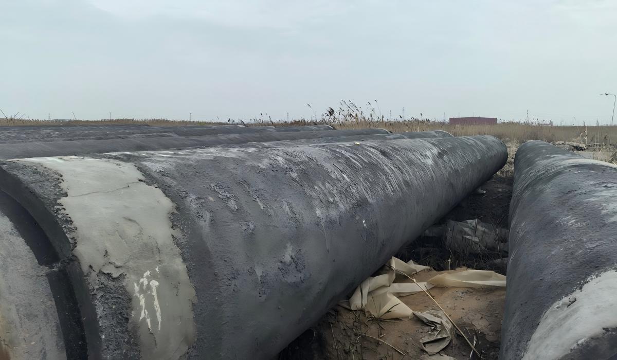 Concrete weight-coated (CWC) line pipe with the concrete cutback visible at each end — ZC supplied this X52M CWC pipe to a project in Africa. The gap at every girth weld is what the infill system must later restore.
On offshore pipelines coated with concrete weight coating (CWC), the factory-applied concrete terminates a short distance from each pipe end, leaving a gap in the concrete OD profile at every girth weld location. This gap must be filled after the anti-corrosion FJC is applied in order to restore the outer diameter of the pipe string, maintain the designed negative buoyancy per metre of pipeline, and protect the underlying anti-corrosion coating from mechanical abrasion during seabed contact and pipe-lay operations.
The anti-corrosion layer is applied first — typically a heat shrink sleeve or liquid epoxy system selected to match the underlying mainline anti-corrosion coating and operating temperature. Once the anti-corrosion coating has cured, an infill compound is cast around the joint using a reusable mould clamped to the concrete OD on both sides of the gap. Common infill materials include polyurethane foam infill for thermally insulated flowlines where continuity of insulation is required, and epoxy paste or cementitious grout infill for standard CWC pipelines where the primary requirement is mechanical profile restoration. Hot-poured asphalt mastic infill is used on some older-specification projects but has largely been superseded by polyurethane and epoxy systems.
The mould-and-pour process requires accurate OD measurement of the adjacent concrete ends, correct mix ratios for two-part infill systems, and degassing of the filled cavity before the infill sets. Standards governing offshore FJC performance include ISO 21809-5 for field joint coatings on offshore pipelines and the DNV pipeline standards. Where the mainline coating and field joint system must also meet sour-service or deepwater constraints, see the pipeline coating selection for sour service and offshore → guide.
DNV pipeline standards have been reissued under updated designations. Verify the current DNV standard designation applicable to the project specification (e.g., DNVGL-ST-F101 or successor document) before citing it in FJC qualification documentation.
Infill systems are inherently more expensive and time-consuming than onshore FJC systems and represent a significant cost driver on deepwater pipe-lay campaigns.
Field Joint Count and Coverage Area per Kilometre
Worked Calculation: Sizing the FJC Scope Before Tendering
Understanding how many field joints a pipeline requires — and how much bare steel area they represent — is essential for both material quantity take-off and cathodic protection (CP) current demand design. This calculation is commonly left to the FJC subcontractor, but coating engineers who verify it before contract award catch scope gaps early.
Standard API 5L pipe is supplied in random lengths R2 (8–13 m) and R3 (greater than 13 m). For a pipeline using standard R2 lengths with average 11 m per joint:
- Field joints per kilometre = 1,000 m ÷ 11 m/joint = 90.9 ≈ 91 field joints per km
- Cutback length each end: 150 mm; total bare length per joint: 150 + 150 = 300 mm
- Bare steel area per field joint (24-inch OD = 609.6 mm): π × 0.6096 m × 0.300 m = 0.574 m² per joint
- Total bare area per km = 91 × 0.574 = 52.2 m² — the area the FJC system must cover per kilometre
- For a 100-km pipeline: 5,220 m² of bare steel at field joints — equivalent to the external surface area of a 24-inch pipe 2.7 km long
This calculation shows why field joint coating quality and holiday rate contribute materially to the overall CP current demand design for the pipeline. At 91 joints/km, a 5% holiday rate at field joints means 4.5 joints/km with unrepaired holidays before burial — far more significant than the same holiday rate on the factory-coated pipe body. Procurement teams specifying FJC material quantities should add a minimum 10% contingency for cutback length variation and repair material.
Comparison: Selecting the Right System
| Factor | HSS | Liquid EP / PU | Infill |
|---|---|---|---|
| Mainline coating compatibility | 3LPE, 3LPP, FBE | Any | CWC, foam insulation |
| Installation speed | Fast (15–20 min) | Slow (multiple coats) | Medium |
| Subsea suitability | To ~200 m (qualified) | Excellent | Essential for CWC |
| Maximum service temperature | 80–110°C | Up to 150°C | 60–80°C (mastic) |
| Relative cost | Low–medium | Medium | High |
| Skill required | Low | High | Medium |
| Geometry flexibility | Limited (flat surfaces best) | Excellent | Moderate |
For a standard onshore 3LPE pipeline operating below 80°C, a three-layer HSS system is the default and most cost-effective choice. Liquid-applied epoxy becomes necessary when the operating temperature exceeds HSS limits, when the geometry is irregular, or when the project specification requires a single FJC system to cover both the onshore sections and a subsea river crossing. Infill systems are non-negotiable wherever the mainline coating includes CWC or foam insulation, because no amount of HSS or liquid coating can restore the concrete profile without a structural infill compound.
Surface Preparation and Holiday Testing
Surface preparation is the single most important variable in FJC performance and the most common point of failure on construction sites working under schedule pressure. The minimum acceptable standard for HSS systems is SSPC-SP6 commercial blast cleaning, though many specifications — and all dual-layer and three-layer HSS specifications — require SSPC-SP10 near-white blast. Liquid-applied and infill anti-corrosion layers mandate SSPC-SP10 as an absolute minimum. Any relaxation of surface prep standards in the field will reduce adhesion and accelerate disbondment, regardless of how well the coating itself is applied.
Holiday testing of the completed FJC is mandatory before backfill or lowering. All completed FJC must achieve zero holidays — no exceptions. For coatings with a specified DFT above 250 µm, a DC high-voltage spark test is conducted at approximately 5 V per micrometre of specified DFT, typically resulting in test voltages of 5–15 kV for 1–3 mm coatings.
The specific holiday test voltage and electrode speed must be confirmed against the project specification and the FJC system manufacturer's data sheet. Applying a voltage derived from nominal DFT without verifying it against the specified DFT for the actual system supplied can result in under-voltage testing that fails to detect pinhole holidays through thick adhesive zones.
For thin coatings below 250 µm, a low-voltage wet sponge test at 67–90 V is used instead. Any holiday detected must be repaired — by removing and replacing the defective area or applying compatible repair compound — and the repaired area must be re-tested and passed before the pipe joint is released.
A common procurement trap: inspection teams on fast-moving spreads sometimes accept FJC joints with minor pinhole holidays on the understanding that repairs will be made before lowering, but the repair is then omitted in the sequence of back-filling activities. Every holiday accepted without immediate repair should be treated as a potential service failure. The inspection hold point for FJC holiday testing must be enforced as a mandatory stop point — no lowering without a signed FJC acceptance record showing zero holidays on that joint.
Field Joint Coating Failure Modes to Specify Against
Three failure modes account for the majority of in-service FJC failures on pipelines supplied to Africa, the Middle East, and South America. Each one is preventable with correct specification and hold-point inspection — none of them are detectable by holiday testing alone.
Failure Mode 1 — Incomplete Adhesive Squeeze-Out
Mechanism: HSS applied without adequate preheat (surface temperature below 60°C). Thermoplastic adhesive does not flow fully across the pipe surface and into the anchor profile. The sleeve appears visually bonded and passes the holiday test — because the PE outer layer is continuous — but the adhesive is non-bonded to the steel underneath in patches. Under thermal cycling, the non-bonded zones lift and create holidays that were never present during testing.
Diagnostic: Manual tap test (knock with a wooden handle) after the sleeve has cooled — a hollow sound versus a solid sound identifies non-bonded zones. Adhesive squeeze-out must be visually confirmed at both sleeve edges and around the full circumference before accepting the joint.
Fix: Verify surface temperature with a calibrated contact pyrometer, not by visual assessment of the sleeve. Require full adhesive squeeze-out at both edges as an absolute acceptance criterion — no edge, no matter how small, is exempt. Include tap test in inspection hold points for 100% of joints.
Failure Mode 2 — Overcoat Window Violation on Liquid Epoxy
Mechanism: First coat of a two-component liquid epoxy FJC applied and cured. Second coat applied after the manufacturer's maximum overcoat window — a pot-life window that can be exceeded due to weather conditions or schedule pressure. The overcoat interval, whether too early or too late, creates an intercoat adhesion failure plane that is not detectable by holiday testing but manifests as coating delamination under thermal or mechanical cycling in service.
Diagnostic: Adhesion pull-off test (ASTM D4541) on a test panel or on the representative pipe joint — failure occurs at the intercoat plane rather than at the steel interface, indicating intercoat adhesion failure rather than steel adhesion failure.
Fix: Record time-from-mixing for every liquid coat component on-site. Include a mandatory hold point for the time-from-mix check before each coat is applied. In hot ambient conditions above 35°C, common in the Middle East and Sub-Saharan Africa, the maximum overcoat window shortens significantly — reduce batch mixing quantities and increase inspection frequency during peak temperature hours.
Failure Mode 3 — CWC Infill Mould Void
Mechanism: Infill compound (polyurethane or epoxy paste) poured into a mould clamped around the field joint after anti-corrosion FJC has been applied. If the mould is not accurately sized to the as-built CWC OD at both cutback ends, the mould-to-concrete interface leaks. Liquid infill escapes before curing. Voids form in the infill, creating a mechanical weak point in the CWC profile. The anti-corrosion layer under the void receives mechanical point-loading during pipe-lay operations.
Diagnostic: After infill cure and mould removal, dimensional check of the infill OD shows local reduction (dip) at void location. On large-diameter pipe, sound-tapping the infill surface detects hollow zones before the pipe is lowered.
Fix: Measure actual CWC OD at both cutback faces before clamping the mould — do not assume the nominal OD. Adjust the mould to the measured OD. For two-part PU infill, verify the A:B mix ratio gravimetrically before each pour, and confirm the mixed material is degassed (check for excessive foam before pouring into the cavity).
When NOT to Use HSS
HSS is the cost-effective default for onshore pipelines, but five conditions make it the wrong choice. Specifying HSS outside these limits results in a field joint system that either fails in service or cannot be installed correctly — and neither outcome is visible at handover.
| Condition | Correct FJC system | Reason |
|---|---|---|
| Operating temperature > 110°C | Liquid epoxy or PU | No HSS grade is rated above 110°C continuous |
| Subsea application > 200 m water depth | Liquid-applied EP or PU | HSS not qualified for deep hydrostatic pressure without project-specific testing |
| Irregular geometry (tees, elbows) | Liquid-applied EP or PU | HSS cannot conform to non-cylindrical surfaces |
| 3LPP mainline at sub-10°C installation | Heat-resistant HSS with field qualification | Standard PE-based HSS is brittle below −10°C; confirm sleeve grade for cold installation |
| Mainline coating includes CWC | Liquid epoxy + infill | CWC profile requires poured infill that HSS cannot provide |
The table above reflects the conditions under which HSS has failed in documented project experience, not just theoretical limits. Cold-climate installation brittleness in particular is underspecified on projects originating in the Middle East or Africa where the engineering team does not anticipate sub-zero installation temperatures — then the pipe string crosses an elevated section or a mountain traverse where night temperatures fall below −10°C.
Purchase Order Guidance
When specifying field joint coatings on a coated line pipe purchase order, the following items must be explicitly stated to avoid ambiguity between the pipe mill, the coating applicator, and the construction contractor.
Specify on the PO or FJC procedure document:
- FJC system type (HSS single / dual / three-layer, liquid EP, liquid PU, infill — state brand or qualification level)
- Applicable standard and class (e.g., DIN 30672 Class C, ISO 21809-3 Type A)
- Minimum surface preparation level (SSPC-SP10 / Sa 2½ ISO 8501-1)
- Required anchor profile range in µm Rz
- Specified DFT (µm) and number of coats for liquid systems
- Holiday test method, voltage, and acceptance criterion (zero holidays)
- Inspection hold points: surface prep verification, DFT check, holiday test sign-off
Critical procurement trap — temperature rating mismatch:
Wrong PO: "Field joint coating: heat shrink sleeve per DIN 30672."
What ships: Contractor sources the cheapest locally available HSS — often a standard grade rated to 60°C. No temperature rating requirement was stated on the PO, so no violation occurs. When the pipeline reaches operating temperature, the HSS adhesive softens, disbondment initiates at the highest-temperature joints first, and corrosion accelerates at precisely the locations that were already the most vulnerable.
Correct PO: "Field joint coating: heat shrink sleeve, DIN 30672 Class C, minimum temperature rating 80°C (or 110°C for high-temperature sections) — temperature rating to match the mainline coating. Provide product data sheet confirming temperature rating before FJC material is approved for use."
Always cross-reference the mainline coating temperature rating against the FJC system data sheet and confirm they are matched before approving the FJC material for use.
Secondary procurement trap — field joint kit scope:
Wrong PO: "FJC system: as per contractor's standard procedure."
What ships: Contractor mobilises with the FJC system they used on the last project — which may have had a different mainline coating, a different temperature rating, and a different surface preparation requirement. The kit scope (whether it includes FBE primer, whether it is a single-layer or three-layer system) is assumed rather than specified.
Correct PO: "FJC system to include: FBE primer [state product], co-polymer adhesive [state product], crosslinked PE outer sleeve [state product and grade], all from the same manufacturer's qualified system. FJC system qualification to be provided prior to mobilisation, evidencing testing against the project temperature rating and burial depth."
A secondary consideration for EPC procurement teams sourcing coated pipe for multi-terrain projects is to align the FJC system specification with the mainline pipe coating documentation from the mill. ZC Steel Pipe provides coating inspection records, holiday test reports, and material data sheets for all factory-applied coatings, giving the field FJC contractor the verified baseline data needed to select and qualify the correct FJC system before mobilisation.
Frequently Asked Questions
What is a field joint coating?
A field joint coating (FJC) is the corrosion protection system applied in the field to the bare steel zone left at each pipe end after factory coating. During production, both ends of a coated pipe are left uncoated — typically 100–150 mm from each end — to allow girth welding. After welding and non-destructive testing, the exposed steel must be coated before backfill or lowering, and the FJC system must match or exceed the corrosion protection level of the mainline factory coating.
How long does a heat shrink sleeve field joint take to install?
A standard heat shrink sleeve (HSS) field joint installation takes approximately 15–20 minutes per joint, making it significantly faster than liquid-applied systems. The procedure includes abrasive blast cleaning, preheating the steel to typically 60–80°C, sliding the sleeve into position, and applying heat with a propane torch to activate shrinkage and bond the thermoplastic adhesive backing to the pipe surface.
Can heat shrink sleeves be used subsea?
Standard heat shrink sleeves are qualified for onshore and shallow buried applications, with subsea use typically limited to approximately 200 m water depth, subject to qualification testing. For deeper subsea applications, liquid-applied epoxy or polyurethane systems are preferred because they conform closely to irregular weld geometry, require no repositioning in water, and can be formulated for elevated hydrostatic pressure and low ambient temperature conditions. Any subsea FJC application should be qualified against the specific project conditions.
What surface preparation is required for liquid epoxy field joint coatings?
Liquid-applied epoxy field joint coatings require near-white blast cleaning to SSPC-SP10 (equivalent to Sa 2½ per ISO 8501-1) as a minimum. The anchor profile should be 50–100 µm Rz per the project specification. The surface must be free of mill scale, rust, contaminants, and moisture at the time of application, and the ambient temperature must remain within the coating manufacturer's stated application window throughout all coats and cure cycles.
Why do CWC pipelines require infill field joint systems?
Concrete weight coating (CWC) is applied to offshore pipelines to provide negative buoyancy and on-bottom stability. The CWC extends to within a short distance of each pipe end, leaving a gap at the girth weld zone. An infill system is required to fill this gap and restore the full outer diameter profile of the concrete, maintain buoyancy calculation integrity along the pipe string, and protect the anti-corrosion layer beneath from mechanical damage during pipe-lay. The anti-corrosion layer under the infill is typically a heat shrink sleeve or liquid epoxy applied first, followed by a polyurethane or epoxy paste infill cast in a mould around the joint.
How is a field joint coating inspected for holidays?
Field joint coatings are holiday-tested using one of two methods depending on coating thickness. For coatings thicker than 250 µm, a DC high-voltage spark test is used at a voltage of approximately 5 V per micrometre of specified dry film thickness, typically 5–15 kV for 1–3 mm coatings per the project specification and coating system data sheet. For thin coatings below 250 µm, a low-voltage wet sponge test at 67–90 V is used. Zero holidays are acceptable — any discontinuity must be repaired and the area re-tested before the joint is approved for backfill or lowering.
What field joint coating system should I specify for a 3LPE-coated onshore pipeline?
For a 3LPE-coated onshore pipeline operating below 80°C, a three-layer heat shrink sleeve system — comprising an FBE primer layer, co-polymer adhesive, and crosslinked polyolefin outer sleeve — is the most common specification because it mirrors the three-layer structure of the mainline coating, provides rapid installation at typically 15–20 minutes per joint, and delivers consistent performance with low skill dependence. Where the operating temperature exceeds 80°C up to approximately 110°C, a heat-resistant HSS grade or a liquid-applied epoxy system should be evaluated in its place.
What are the main causes of field joint coating failures?
The most common causes of field joint coating failure are inadequate surface preparation — where residual mill scale or rust beneath the coating creates disbondment initiation sites — insufficient preheat before HSS application resulting in incomplete adhesive bonding, mismatched temperature rating between the FJC system and the mainline coating, and accepted holidays that were not repaired before backfill. A secondary cause is mechanical damage during backfill from sharp rock or hard lumps impacting the joint zone before protective padding is placed; this is particularly common in rocky terrain where padding specifications are not enforced at the trench.