
Concrete weight coating is a critical component of offshore pipeline system design, providing the negative buoyancy required for seabed stability across water depths from shallow coastal zones to deepwater developments. Without CWC, most offshore pipelines would require extensive anchoring systems or rock dumping to remain stable on the seabed under hydrodynamic loading and during installation. CWC is the most cost-effective ballasting solution for the vast majority of offshore pipeline projects.
ZC Steel Pipe supplies coated line pipe for offshore projects including coordination of concrete weight coating application. We supply API 5L line pipe with FBE and 3LPP anti-corrosion coating followed by CWC application at qualified yards — the 3LPE / FBE / 3LPP coating selection guide → covers the anti-corrosion layer that goes under the concrete. This guide covers CWC specifications, design principles, anti-corrosion coating compatibility, and procurement considerations for offshore pipeline projects.
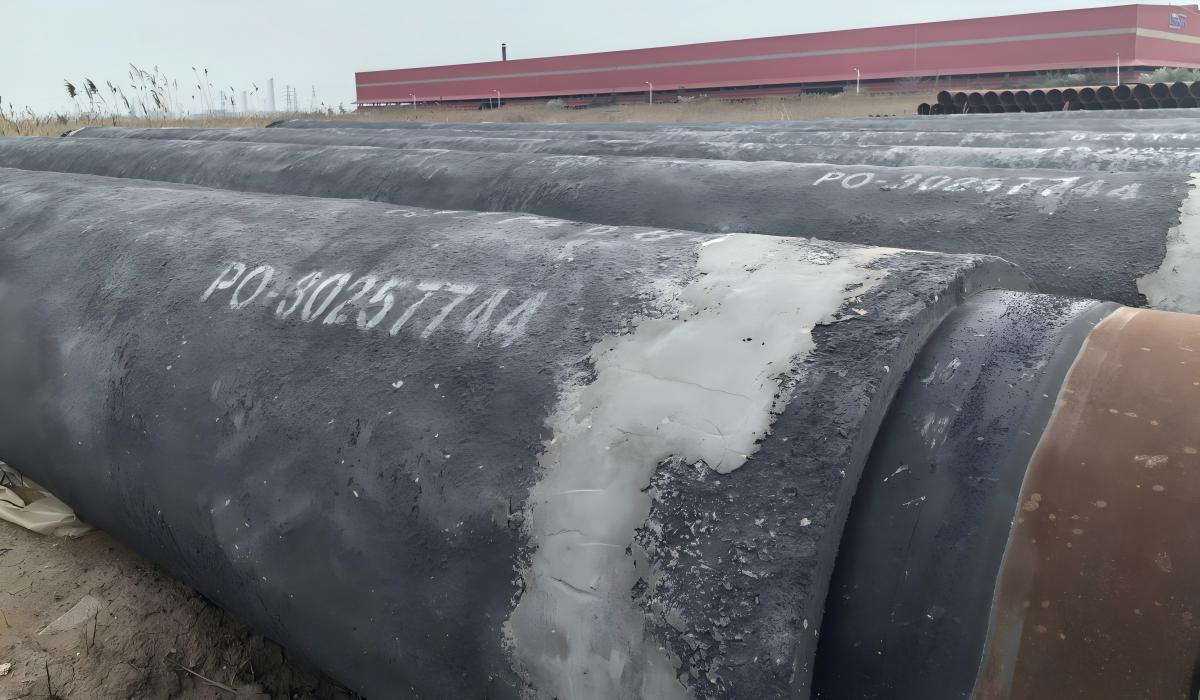 CWC pipe: grey high-density concrete over a black 3LPE anti-corrosion layer, with the cutback band at the end.
What we see on offshore projects: On a West Africa pipeline project, the CWC specification stated "3,040 kg/m³ nominal density, 60 mm nominal thickness" without specifying a minimum density or a tolerance band. The CWC yard applied concrete averaging 2,940 kg/m³ — within any reasonable interpretation of "nominal." The buoyancy calculation had used 3,040 kg/m³ (mid-range). As-built average density was 3.3% below design: the on-bottom stability margin dropped from the designed 1.15 to approximately 1.07. During a storm current event, a 400-metre section of pipeline moved laterally. Specify minimum density, not nominal density — and require density verification records per pipe joint, not per concrete batch.
1. Why Offshore Pipelines Need Weight Coating
An empty steel pipeline has a bulk density of approximately 1,200–1,500 kg/m³ depending on OD, wall thickness, and any internal coating — significantly less than seawater at 1,025 kg/m³ (shallow) to 1,035 kg/m³ (deepwater). An empty pipe will float.
Even when filled with crude oil (typically 800–870 kg/m³), a pipeline may have insufficient negative buoyancy to remain stable on the seabed against:
- Hydrodynamic uplift from wave-induced oscillating pressure
- Current drag in areas with strong tidal or deepwater currents
- Installation loads during S-lay or J-lay installation
- Slope stability on inclined seabed terrain
CWC provides the additional weight — typically 500–1,500 kg/m of pipe — required for seabed stability throughout the pipeline operating life.
2. CWC Design Parameters
Pipeline engineers calculate the required CWC density and thickness based on:
| Parameter | Effect on CWC Design |
|---|---|
| Pipe OD and wall thickness | Determines steel weight and buoyancy |
| Water depth | Affects hydrostatic pressure and hydrodynamic loading |
| Content density | Heavy crude requires less CWC than gas or light oil |
| Seabed conditions | Soft seabed may require additional stability margin |
| Current velocity | Higher currents require more negative buoyancy |
| Installation method | S-lay, J-lay, and reel-lay have different tension requirements |
| Design factor (safety margin) | Typically 1.1–1.3× minimum required weight |
The design factor is the parameter most often underspecified. A design margin of 1.15 means 15% more net downward force than the minimum required for stability — but as the West Africa case above illustrates, that margin can be consumed entirely by a density tolerance band that was never explicitly constrained.
Buoyancy calculation example:
For a 16-inch (406.4mm) OD, 12.7mm wall API 5L X65 gas pipeline in 100m water depth:
- Steel weight: ~123 kg/m
- Empty buoyancy (upward force): ~132 kg/m
- Net buoyancy (empty): +9 kg/m (floats)
- Required negative buoyancy: minimum 15–20 kg/m (with safety factor)
- Required CWC: approximately 40–60mm at 3,040 kg/m³ density
For the underlying line pipe grade specifications, see the API 5L specification tables →
The base pipe for CWC trunklines is typically large-diameter welded (LSAW / HSAW) line pipe — see seamless vs welded line pipe selection →. Higher-pressure trunklines specified in API 5L X70 follow the same buoyancy method as the X65 example above.
To verify the base pipe design pressure, use the Pipeline Design Calculator →
Density Sensitivity: Impact of Density Tolerance on On-Bottom Stability
Using the same 16-inch example (406.4 mm OD, 12.7 mm wall, 60 mm CWC nominal thickness), the following shows how a 3.3% shortfall in concrete density erodes the stability margin:
Step 1 — CWC cross-section geometry:
- Steel pipe outer radius: 406.4 ÷ 2 = 203.2 mm = 0.2032 m
- CWC outer radius: 0.2032 m + 0.060 m = 0.2632 m
- CWC cross-section area per metre: π × (0.2632² − 0.2032²) = π × (0.06927 − 0.04129) = π × 0.02798 = 0.08791 m²/m
Step 2 — CWC weight at design density (3,040 kg/m³):
- 0.08791 m²/m × 3,040 kg/m³ = 267.2 kg/m
Step 3 — CWC weight at 2,940 kg/m³ (100 kg/m³ below design):
- 0.08791 m²/m × 2,940 kg/m³ = 258.4 kg/m
- Weight reduction from density shortfall: 267.2 − 258.4 = 8.8 kg/m
Step 4 — Impact on stability margin:
If the design on-bottom stability margin was 15 kg/m net negative buoyancy (stability factor 1.15):
- At 2,940 kg/m³: net negative buoyancy = 15 − 8.8 = 6.2 kg/m
- Stability factor drops from 1.15 to approximately 1.06 — a 14-percentage-point reduction
- A 100 kg/m³ density shortfall (3.3% below design density) eliminates 59% of the stability margin
This calculation is why density tolerance must be specified as a minimum value — for example, 2,990 kg/m³ minimum on any individual core sample — not a nominal with undefined tolerance. A specification that reads "3,040 kg/m³ nominal" permits 2,900 kg/m³ deliveries that are technically compliant but structurally inadequate for the stability design.
3. CWC Specifications
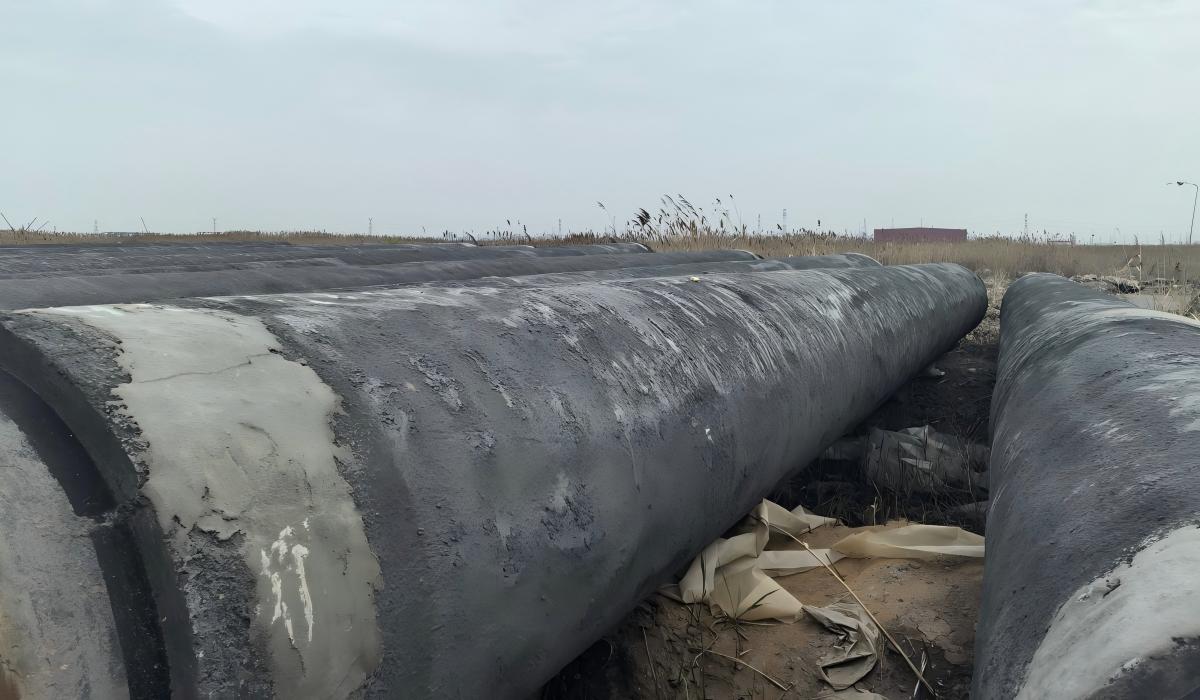 CWC-coated pipe joints in the field, concrete cut back at each end to expose the anti-corrosion layer.
Concrete density options:
| Density Class | Density (kg/m³) | Aggregate Type | Typical Application |
|---|---|---|---|
| Standard | 2,900–3,000 | Magnetite or ilmenite | Most offshore pipelines |
| High density | 3,000–3,200 | Magnetite + barite | Small OD, deepwater |
| Ultra-high density | 3,200–3,400 | Barite or hematite | Special applications |
The density class selected directly determines which aggregate system is used at the CWC yard. Magnetite (Fe₃O₄) achieves 2,900–3,100 kg/m³ routinely; ilmenite (FeTiO₃) is similar; barite (BaSO₄) is required to push above 3,200 kg/m³. The aggregate selection affects both cost and mix design — verify the aggregate source in the yard's procedure qualification documents, not just the certificate numbers.
Concrete density is a function of aggregate specific gravity and mix void content — not of compressive strength. A mix optimised for maximum compressive strength may use different aggregate packing than one optimised for maximum density. A 3,200 kg/m³ CWC can have the same compressive strength as 2,900 kg/m³ CWC, and vice versa. Specifying minimum compressive strength without a minimum density requirement gets you a conforming mix that may achieve high compressive strength with a lighter aggregate blend — and inadequate ballast. Density and compressive strength must be separately specified as independent acceptance criteria.
Standard CWC thicknesses:
| Thickness | Common Application |
|---|---|
| 40mm | Large OD pipe, mild conditions |
| 60mm | Standard offshore trunkline |
| 80mm | Smaller OD, higher current areas |
| 100mm | Maximum standard thickness |
Reinforcement: CWC includes a wire mesh cage (typically 3.0–4.0mm wire diameter, 50×50mm mesh) embedded in the concrete for mechanical reinforcement and crack control. The wire cage is placed concentrically around the anti-corrosion coating before concrete impingement.
Cutback: The concrete ends are cut back from each pipe joint end to expose the anti-corrosion coating. Standard cutback length is 150–300mm per end, to allow field joint welding and field joint coating during installation.
What we ship in CWC: The most demanding coated spec we handle is large-diameter LSAW with 3LPE plus a concrete weight coat. On our X52M PSL2 28-inch CWC supply to Africa — 350 pcs — the CWC was specified at 70 mm minimum per ISO 21809-5 over a 3LPE anti-corrosion layer per ISO 21809-1. We see the concrete called out to a minimum thickness on these POs, never a nominal figure, because the negative-buoyancy calculation the pipe has to satisfy on the seabed depends on the mass that minimum guarantees.
4. Anti-Corrosion Coating Compatibility
CWC is applied over an anti-corrosion coating. The standard combinations:
| Anti-Corrosion Coating | CWC Compatibility | Application |
|---|---|---|
| FBE (single layer) | Excellent — standard | Most offshore pipelines |
| 3LPP | Good — used for hot service | High temperature flowlines |
| 3LPE | Limited — lower mechanical resistance | Shallow water, mild conditions only |
FBE under CWC: FBE is the preferred anti-corrosion coating under CWC. The thin FBE layer (300–500 µm) provides excellent adhesion to the steel surface and good chemical resistance to seawater, while its mechanical properties are compatible with the concrete impingement process. FBE also has good compatibility with cathodic protection systems used on offshore pipelines.
3LPP under CWC: 3LPP is used under CWC for high-temperature flowlines where operating temperature exceeds the 80°C limit of FBE. The PP outer layer provides better temperature resistance but requires careful concrete application to avoid delamination during impingement.
5. Testing and Quality Control
CWC application is subject to the following quality controls per DNV-ST-F101 and project specifications:
| Test | Frequency | Purpose |
|---|---|---|
| Density verification | Every batch | Confirm design density achieved |
| Thickness measurement | 100% — every joint | Confirm minimum thickness |
| Holiday test (anti-corrosion) | 100% before CWC | Confirm anti-corrosion coating integrity |
| Adhesion test | Sample basis | Confirm concrete-to-AC coating bond |
| Compressive strength | Every batch | Confirm concrete mix strength |
| Wire mesh inspection | Every joint | Confirm reinforcement placement |
| Impact test | Sample basis | Confirm resistance to installation damage |
| Cutback inspection | Every joint | Confirm correct cutback dimensions |
Density verification "per batch" is the default DNV-ST-F101 language — but as the sensitivity calculation in Section 2 demonstrates, batch averages can mask per-joint variation. For critical stability-limited applications, upgrade the density verification requirement to per-joint core sampling. This adds cost (approximately 2–3% of CWC application cost) but eliminates the scenario where individual joints are below the design density that was never specified as a minimum.
6. Field Joint Coating
Field joints — the uncoated sections at each pipe joint end after girth welding during installation — must be coated and weighted after welding, an operation covered in detail in the field joint coating systems guide →. Standard field joint coating systems for CWC pipelines:
| System | Anti-Corrosion | Weight | Application |
|---|---|---|---|
| Heat-shrink sleeve + moulded PP | Heat-shrink | Injection-moulded PP | Standard for 3LPP pipelines |
| Liquid epoxy + PP half-shells | Liquid epoxy | PP half-shells | Alternative for 3LPP |
| Liquid epoxy + concrete | Liquid epoxy | Poured concrete | Standard for FBE/CWC pipelines |
| FBE + concrete | FBE | Poured concrete | Premium for FBE/CWC |
Field joint design must be specified and qualified before pipeline installation begins.
7. Procurement Guidance
When procuring coated line pipe with CWC for an offshore project, specify:
Pipe specification:
- API 5L grade, PSL level, OD, wall thickness, length
- End finish (bevelled ends, cutback dimensions)
Anti-corrosion coating:
- FBE or 3LPP, thickness, standard (ISO 21809-1 or -2)
- Holiday test voltage, adhesion requirements
CWC specification:
- Concrete density (kg/m³)
- Nominal thickness (mm) and tolerance
- Reinforcement wire specification
- Compressive strength requirement
- Cutback length (each end)
- Reference standard (DNV-ST-F101, ISO 21809-5)
Testing and documentation:
- MTC format (EN 10204 3.2)
- Third-party inspection scope
- CWC batch records and test reports
- Anti-corrosion coating inspection records
Procurement trap — wrong PO text and what ships:
Wrong PO: "DNV-ST-F101 CWC: 3,040 kg/m³ nominal density, 60 mm nominal thickness, wire mesh reinforcement."
What ships: The yard produces concrete to the batch average density as measured from cube samples per shift. Some joints receive 2,920 kg/m³, others 3,100 kg/m³. The batch average passes, but individual joints are below the design density used in the stability calculation. No per-joint density record is produced — only batch certificates. The yard is fully compliant with the PO as written.
Correct PO: "DNV-ST-F101 CWC: minimum density 2,990 kg/m³ on any individual core sample; nominal thickness 60 mm, tolerance −0/+10 mm; compressive strength minimum 40 MPa at 28 days; per-joint density records required, not batch averages; wire mesh minimum 3.5 mm diameter, 50×50 mm mesh, concentric placement verified; cutback 200 mm ± 20 mm each end."
ZC Steel Pipe coordinates the full supply chain for offshore coated line pipe — API 5L pipe, anti-corrosion coating (FBE or 3LPP), and CWC application — from our supply network. Contact us with your project specification for availability and lead time.
CWC Failure Modes to Specify Against
Three failure modes appear repeatedly on CWC projects. Each can be prevented by specification language — none of them are caught by standard DNV-ST-F101 batch testing alone.
Failure Mode 1 — Aggregate Segregation by Clock Position
Mechanism: High-density aggregate (magnetite, ilmenite) has higher specific gravity than the cement matrix. If the impingement mix is too wet or pipe rotation speed is too low during CWC application, the heavy aggregate settles toward the bottom of the rotating pipe during application. The lower half (6 o'clock position) receives higher-density concrete; the upper half (12 o'clock) receives lower-density concrete. The cross-section density varies by more than 100 kg/m³. The average density may pass batch testing, but the upper-half section has insufficient mass for the stability calculation.
Diagnostic: Core samples taken at the 12 o'clock and 6 o'clock positions from the same concrete cross-section show density variation greater than 100 kg/m³. Require at least two core positions per sampled joint to detect segregation.
Fix: Specify maximum density variation across the cross-section on the QC plan — for example, no individual core more than 100 kg/m³ below the target minimum. Verify pipe rotation speed and mix water content as controlled variables in the CWC application procedure qualification. The rotation speed and slump specification must appear as hold points in the procedure, not as advisory notes.
Failure Mode 2 — Anti-Corrosion Coating Holiday Undetected Under CWC
Mechanism: FBE or 3LPP anti-corrosion coating is applied and inspected for holidays. A coating repair is made at a detected holiday but the repair is improperly applied — incompletely cured or unbonded. The pipe then proceeds to CWC application. CWC covers the undetected or poorly repaired holiday. The holiday cannot be detected after CWC application by any routine method. Corrosion initiates under the CWC at the holiday location and proceeds undetected for years.
Diagnostic: Discovered only at an ILI run (MFL or UT) identifying an external corrosion anomaly, or at excavation triggered by a potential survey anomaly, or at pipeline failure. The failure mode is impossible to detect by routine surveillance methods once CWC is applied.
Fix: Mandatory hold point — 100% holiday test of the anti-corrosion coating with written sign-off by the QC inspector immediately before CWC application. No concrete without a signed FBE holiday test completion record for that pipe joint. Re-test any joint where the anti-corrosion coating has been disturbed after the initial holiday test. This hold point must appear in the inspection and test plan (ITP) as a witness point requiring QC sign-off, not as a review point.
Failure Mode 3 — Freeze-Thaw Cracking During Cold Climate Storage
Mechanism: CWC is applied and then stored or transported in temperatures below freezing before the concrete has achieved adequate strength (typically the 28-day design strength). Water in the concrete pore structure freezes, expands, and creates micro-cracking through the concrete depth. The cracking reduces the mechanical protection the concrete provides during installation, and in the worst case reduces the effective density — cracked zones have lower bulk density than design due to void formation from ice expansion.
Diagnostic: Visual cracking on the CWC surface visible at pipe ends. Impact test results below specification minimum. Density measurements on cores taken from cracked sections are lower than the design density due to void formation from ice expansion.
Fix: Specify minimum concrete temperature of 5°C during curing and a minimum cure time of 24 hours above 5°C before any outdoor exposure to freezing conditions. For projects in cold climates, include a cold weather protection protocol — insulated tarpaulin or heated storage — in the CWC application procedure. Require compressive strength verification at the actual curing temperature, not at the standard 20°C laboratory condition.
When NOT to Use CWC
CWC solves one problem — negative buoyancy for offshore seabed stability — and it does that well. For the applications below, CWC is either the wrong tool or actively incompatible with the installation method:
| Pipeline application | Alternative | Reason |
|---|---|---|
| Onshore buried pipeline | Trench anchoring or bentonite slurry | CWC is an offshore ballasting solution; onshore pipelines use mechanical anchoring |
| Reel-lay installation | Flexible pipe or concrete saddle weights | CWC cracks during reeling; cannot be applied to reel-lay pipe |
| Deepwater flow assurance priority | Syntactic foam insulation | Where thermal insulation is required, insulation coating replaces CWC as the primary outer layer |
| Very large diameter pipe already close to negative buoyancy | Reduced CWC thickness or no CWC | Some 48-inch and larger pipe with thick walls is already adequately negative buoyant with FBE alone |
| Pipe with required tight-radius curves | Pre-bent bare pipe with saddle weights | CWC stiffens pipe and prevents curvature after application |
The reel-lay incompatibility is the one most often discovered late in a project. Reel-lay vessels impose a tight bend radius on the pipe during reeling — typically 7–12 m on modern vessels — that cracks any concrete coating regardless of mix design or thickness. If the installation method is not confirmed before coating specification, a CWC specification can be written, qualified, and partially procured before the incompatibility is identified. Verify the installation method before finalising the coating specification.
ZC Steel Pipe supplies API 5L line pipe with FBE and 3LPP anti-corrosion coating for offshore projects. For projects where CWC is the correct solution, we coordinate application at qualified yards with DNV-ST-F101 qualified procedures. Contact us with your pipe specification, installation method, and target CWC density for availability and lead time.
Frequently Asked Questions
What is concrete weight coating and why is it used on offshore pipelines?
Concrete weight coating (CWC) is a layer of reinforced concrete applied over the anti-corrosion coating of an offshore pipeline to provide negative buoyancy — making the pipeline heavy enough to sink and remain stable on the seabed without additional anchoring. Steel pipe is inherently buoyant when empty and marginally negative when filled with product, but hydrostatic uplift forces on the seabed and hydrodynamic forces from currents and waves require additional weight. CWC provides this weight cost-effectively compared to other ballasting methods.
What density is used for offshore pipeline concrete weight coating?
Offshore pipeline CWC uses high-density concrete with a typical density of 2,900–3,200 kg/m³, compared to standard structural concrete at 2,300 kg/m³. The higher density is achieved by using heavy aggregate materials — typically magnetite (iron ore), ilmenite, or barite — instead of standard sand and gravel. The required density is specified by the pipeline engineer based on the buoyancy calculation for the specific pipe OD, wall thickness, content density, water depth, and seabed stability requirements.
What thickness of concrete weight coating is typically applied?
CWC thickness for offshore pipelines typically ranges from 40mm to 100mm depending on the buoyancy requirement. Standard thicknesses are 40mm, 60mm, 80mm, and 100mm. Thinner coatings (40–60mm) are used for large diameter pipes that are already close to neutral buoyancy. Thicker coatings (80–100mm) are required for smaller diameter pipes or applications with high hydrodynamic loading. The required thickness is calculated by the pipeline engineer for each specific project.
What anti-corrosion coating is compatible with concrete weight coating?
FBE (Fusion Bonded Epoxy) is the standard anti-corrosion coating applied under concrete weight coating for offshore pipelines. FBE provides good adhesion to the steel surface, chemical resistance to seawater, and mechanical compatibility with the concrete application process. 3LPP (Three-Layer Polypropylene) is also used under CWC for high-temperature flowlines. 3LPE is generally not recommended under CWC for deepwater applications due to its lower mechanical resistance to the concrete application impact and lower temperature rating.
How is concrete weight coating applied to pipeline pipe?
CWC is applied by the impingement process: a cage of reinforcing wire mesh is placed around the anti-corrosion coated pipe, then high-density concrete is impinged (sprayed under pressure) onto the rotating pipe to build up the specified thickness. The concrete is compacted during application and cured before the pipe is handled or loaded. The process requires specialised CWC application facilities — not all coating yards have this capability. ZC Steel Pipe coordinates CWC application at qualified yards.
Does concrete weight coating affect pipeline installation?
Yes — CWC significantly affects pipeline installation. The increased pipe weight and OD affect the allowable installation vessel tension, stinger design, and abandonment and recovery loads. CWC also affects field joint coating — the concrete ends must be cut back to expose the anti-corrosion coating at each pipe joint end (the cutback), and field joints must be coated and weighted after welding during installation. The cutback length and field joint design are specified by the project pipeline engineer.
What standards govern concrete weight coating for offshore pipelines?
The primary standard for offshore pipeline CWC is DNV-ST-F101 (Submarine Pipeline Systems), which specifies requirements for coating system design, material properties, application quality, and testing. ISO 21809-5 also provides requirements for external concrete coatings. Project specifications typically reference one or both of these standards with additional project-specific requirements for density, thickness, reinforcement, and testing.
Can concrete weight coating be applied to coiled pipe or small diameter pipe?
CWC is typically applied to straight pipe joints (12m lengths) and is not suitable for coiled pipe due to the rigid nature of the concrete coating. For small diameter pipe (below approximately 4 inches OD), alternative weight coating methods such as solid PP weight coating or saddle weights are sometimes used instead of CWC, as the concrete thickness required for buoyancy control relative to the pipe OD becomes impractical.