
Coating selection for sour service and offshore pipelines requires evaluation of more parameters than standard onshore sweet service applications. The external environment (buried vs subsea vs splash zone), the operating temperature, the cathodic protection system design, and any H₂S or CO₂ in the transported fluid all influence the appropriate coating specification. Getting the coating right at the design stage prevents the costly consequences of premature coating failure — pipeline corrosion, integrity threats, and unplanned maintenance.
ZC Steel Pipe supplies coated line pipe for sour service and offshore applications, with FBE, 3LPE, 3LPP, and CWC coating applied at our Hai'an City coating facility to ISO 21809 and project specifications. This guide covers coating selection for sour service buried pipelines, offshore subsea pipelines, high-temperature flowlines, and splash zone applications.
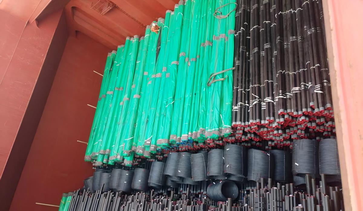 ZC X70Q sour-service line pipe, 3LPE-coated and bundled, loaded in the vessel hold for shipment to a Nigerian gas operator.
What we see on sour gas projects: On a Middle East sour gas gathering line, the project specified 3LPE external coating with cathodic disbondment ≤ 12 mm radius at 65°C per ISO 21809-1. The MTC showed the CD test result at exactly 12 mm — passing. What the project team did not check: the test was conducted at 65°C, but the pipeline operating temperature at peak summer soil conditions reached 55°C and the specification's cathodic disbondment test temperature was the ISO default, not the project's actual operating temperature. In aggressive H₂S-active soil, the 12 mm result at 65°C translates to a narrower safety margin at 55°C in a warm climate with SRB activity. Specifying ≤ 8 mm at 65°C costs nothing extra at the mill and provides meaningful additional margin on sour service pipelines.
1. Coating Selection Framework
The primary parameters driving coating selection for sour service and offshore applications:
| Parameter | Impact on Coating Selection |
|---|---|
| Operating environment | Buried / subsea / splash zone / above ground |
| Operating temperature | Drives FBE vs 3LPE vs 3LPP selection |
| H₂S in soil/water | Increases cathodic disbondment risk |
| Water depth (offshore) | Drives CWC requirement |
| Pipeline service | Gas / liquid / injection — affects internal coating |
| Cathodic protection | CP design links to coating quality |
| Installation method | Affects mechanical protection requirement |
| Project standard | DNV, ISO, client spec |
Read this table as a pre-FEED checklist, not a post-design confirmation. Coating system decisions made after the pipe has been ordered are expensive to unwind — the mill cannot add a 3LPP topcoat to FBE-coated pipe already in production. Every cell in this table should have an answer before the coating spec is issued for procurement. For the head-to-head between the three external systems, see the 3LPE vs FBE vs 3LPP coating selection guide.
2. Sour Service Buried Pipelines
For buried sour service onshore pipelines, the coating selection differs from sweet service primarily in quality requirements rather than coating type:
Standard specification — sour service buried pipeline:
| Component | Specification |
|---|---|
| Pipe material | API 5L PSL2 + SR15C (HIC tested) |
| External coating | 3LPE or FBE + 3LPE |
| Coating standard | ISO 21809-1 |
| Cathodic disbondment | Enhanced limit — max 8 mm radius at 65°C (ISO 21809-1) |
| Holiday test | 100% — tighter voltage per enhanced spec |
| Adhesion | Enhanced — minimum 35 N/mm peel strength |
| CP system | Impressed current or sacrificial — designed with coating |
Why 3LPE is preferred over FBE alone for sour service buried pipe: 3LPE provides superior mechanical protection (impact, abrasion) during installation in rocky terrain. In sour service environments where coating damage risk is high, the PE outer layer provides better protection against installation damage that could create holidays in the anti-corrosion layer.
Cathodic disbondment requirement: For sour service buried pipelines, the cathodic disbondment test requirement is often more stringent than standard — maximum 8 mm radius at 65°C vs 15 mm for standard service. This ensures the coating maintains adhesion when CP current passes through holidays in H₂S-rich soil environments.
For the underlying line pipe grade specifications, see the API 5L specification tables →, and for the HIC and SSC material requirements that carry the sour-service duty, the NACE MR0175 / ISO 15156 sour-service limits.
To verify the base pipe design pressure, use the Pipeline Design Calculator →
Sour service changes the coating requirement indirectly — not because H₂S attacks the 3LPE polymer (it does not), but because sour service tightens the required cathodic protection potential from −850 mV CSE (sweet service per NACE SP0169) to −950 mV CSE (SRB-active environments). The more negative CP potential drives higher cathodic current at coating holidays. Higher cathodic current accelerates cathodic disbonding at those holidays. This is the chain: sour environment → tighter CP potential → more current at holidays → faster disbonding. The coating specification change for sour service is therefore in the cathodic disbondment test limit (tighter), not in the coating chemistry.
What we ship for sour buried service: The job closest to this section's scope is our repeat multi-year supply of 6-inch SCH 160 X70Q PSL2 sour-service pipe with 3 mm 3LPE to a Nigerian gas operator — 6,000 pcs, Annex-H and NACE TM0284 HIC qualified, coated to DIN 30670 for direct burial. What we see on these POs matches the pattern above: the sour requirement is handled in the pipe metallurgy (HIC testing, controlled carbon equivalent), while the 3LPE coating is chosen for mechanical protection during burial, not for H₂S resistance itself.
3. Offshore Subsea Pipelines
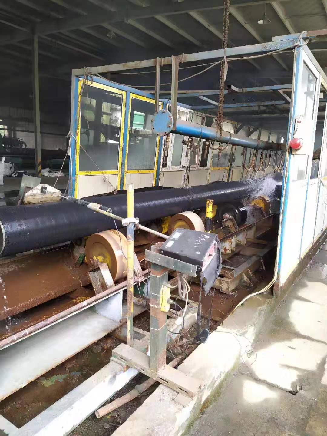 3LPE application in progress on the ZC coating line — the pipe rotates through the coating and cooling station that builds up the layered external system.
Offshore subsea pipeline coating systems are driven by water depth, temperature, and the requirement for concrete weight coating (CWC):
Standard offshore pipeline coating system:
| Pipeline Type | Anti-Corrosion Coating | Weight Coating | Temp Limit |
|---|---|---|---|
| Gas transmission (sweet) | FBE 300–500 µm | CWC 40–100 mm | 95°C |
| Oil transmission | FBE 300–500 µm | CWC 40–100 mm | 95°C |
| Hot oil flowline | 3LPP | CWC 40–100 mm | 110–130°C |
| Gas riser | 3LPP (submerged) + splash zone system | None | 110°C |
| Subsea spool/jumper | 3LPP | None | 110°C |
| Deepwater (>500 m) | FBE or 3LPP | CWC (higher density) | Project specific |
The temperature column is the most critical selection driver — it determines which coating system is physically capable of performing at operating conditions. Specifying FBE on a 90°C flowline is not conservative; FBE's 95°C rating leaves almost no margin for upset conditions or solar gain at the riser section.
Coating system for offshore sour service pipelines: Offshore sour service pipelines (H₂S-containing) use the same external coating systems as sweet service offshore pipelines — the sour service requirement is in the pipe material (PSL2 + HIC test + SSC test) and in the internal corrosion management, not the external coating. External FBE or 3LPP with CWC is standard regardless of H₂S content in the transported fluid.
4. High-Temperature Flowlines
For flowlines with operating temperatures above 80°C — common in EOR, heavy oil, and high-temperature gas condensate fields — 3LPP is required:
| Temperature Range | Coating | Notes |
|---|---|---|
| < 60°C | 3LPE standard | Standard buried or subsea |
| 60–80°C | 3LPE or 3LPP | 3LPP preferred near upper limit |
| 80–110°C | 3LPP standard | 3LPE not acceptable |
| 110–130°C | 3LPP high-temp grade | Confirm specific product rating |
| > 130°C | Thermal insulation coating or CRA | 3LPP limit exceeded |
The 80°C boundary between 3LPE and 3LPP is a hard material limit, not a conservative margin. Polypropylene (3LPP) retains its mechanical and adhesion properties above 80°C where polyethylene (3LPE) softens. At peak upset temperatures — flowline start-up, pigging operations — the 80°C boundary may be crossed even on pipelines with 70°C design temperature. Specify 3LPP wherever the operating temperature band approaches the limit.
3LPP for subsea high-temperature flowlines: Deepwater production flowlines from high-temperature reservoirs combine high operating temperature with hydrostatic external pressure at depth. 3LPP provides the temperature resistance, while its mechanical properties resist the hydrostatic pressure at depth. For deepwater HPHT flowlines, thermal insulation coating systems (FCKM or syntactic foam) may be required in addition to anti-corrosion coating.
5. Splash Zone Coating
The splash zone — typically defined as from −2 m to +5 m relative to mean sea level — is the most aggressive pipeline coating environment:
Splash zone challenges:
- Alternating wet and dry cycling — no continuous CP protection
- UV exposure — degrades many polymer coatings
- Mechanical wave action and debris impact
- Biofouling at the water line
- Thermal cycling from sun exposure and seawater immersion
Standard splash zone coating systems:
| System | Components | Typical DFT |
|---|---|---|
| Three-coat epoxy/PU | Epoxy primer + epoxy midcoat + PU topcoat | 500–800 µm |
| Thermally sprayed aluminium (TSA) | Arc-sprayed aluminium + sealant | 200–300 µm |
| High-build epoxy | High-build epoxy + polyurethane | 600–1,000 µm |
| Monel sheathing | Nickel-copper alloy sheathing | Solid metal |
The DFT column matters because application cost is roughly proportional to thickness and number of coats. TSA at 200–300 µm appears cost-competitive with three-coat epoxy/PU until you account for the specialist equipment required for arc-spraying — it is not a yard-portable process. For sour service platforms with H₂S in the splash zone atmosphere, thermally sprayed aluminium (TSA) provides excellent long-term performance as it is not affected by H₂S and provides sacrificial galvanic protection at coating defects.
6. Cathodic Protection Integration
External coating and cathodic protection must be designed together:
CP current demand vs coating quality:
| Coating System | Typical CP Current Density (mA/m²) |
|---|---|
| Bare steel | 20–100 |
| FBE (aged, with holidays) | 0.5–2.0 |
| 3LPE (new) | 0.01–0.05 |
| 3LPE (aged) | 0.1–0.5 |
| 3LPP | 0.01–0.1 |
Better coating quality reduces CP current demand — smaller and fewer sacrificial anodes offshore, or lower impressed current output onshore. This directly reduces lifecycle cost.
CP shielding risk: Disbonded coating that lifts away from the pipe surface can shield the steel from CP current — the disbonded area is neither protected by coating nor by CP, creating a corrosion risk. FBE has the best cathodic disbondment resistance and lowest CP shielding risk. 3LPP field joints require careful design to prevent CP shielding at the joint interface.
CP Current Demand: Coating Quality Comparison
The CP current demand calculation below demonstrates why coating quality determines rectifier size, station spacing, and anode bed cost — not just coating material cost.
For a 10-km segment of 24-inch (609.6 mm OD) buried pipeline:
Total pipe surface area = π × 0.6096 m × 10,000 m = 19,145 m²
Scenario A — 3LPE at commissioning (holiday rate 0.01% bare steel):
- Bare steel area = 19,145 × 0.0001 = 1.91 m²
- CP current density at holidays: 15 mA/m² (moderate soil)
- CP current demand = 1.91 × 15 = 28.7 mA
Scenario B — FBE only at commissioning (holiday rate 0.05%):
- Bare steel area = 19,145 × 0.0005 = 9.6 m²
- CP current demand = 9.6 × 15 = 144 mA (5× higher than 3LPE)
Scenario C — 3LPE at end-of-life / 30 years (holiday rate 0.1%):
- Bare steel area = 19,145 × 0.001 = 19.1 m²
- CP current demand = 19.1 × 15 = 287 mA (10× initial demand)
The CP rectifier must be designed for the end-of-life current (287 mA) not the commissioning current (28.7 mA). This 10× factor is why NACE SP0169 requires end-of-life design, and why coating quality directly determines the rectifier size, station spacing, and anode bed cost. A project that specifies FBE only to save coating cost at procurement typically pays a larger penalty in CP infrastructure and anode replacement over the pipeline life.
7. Summary — Coating Selection by Application
| Application | External Coating | Internal Coating | CWC |
|---|---|---|---|
| Sour service buried onshore | 3LPE (enhanced CD spec) | Internal FBE if high WC | No |
| Sweet gas buried onshore | 3LPE standard | Internal FBE (flow efficiency) | No |
| Offshore sweet gas trunkline | FBE | Internal FBE | Yes |
| Offshore hot oil flowline | 3LPP | Internal FBE | Yes |
| Offshore subsea sour | FBE or 3LPP | Internal FBE or inhibitor | Yes |
| Deepwater HPHT flowline | 3LPP + thermal insulation | CRA or internal FBE | Project specific |
| Riser — splash zone | 3LPP + splash zone system | — | No |
| CO₂ injection — dry | 3LPE | Bare (dry CO₂) | Project specific |
| CO₂ injection — wet | 3LPE | Internal FBE or CRA | Project specific |
Read across each row: the external coating, internal coating, and CWC requirement are interdependent. A sour service buried pipeline with a water cut above 30% needs both the enhanced CD external spec and internal FBE — specifying one without the other addresses only half the corrosion risk.
When NOT to Specify 3LPE
3LPE is the correct default for most buried onshore pipelines up to 80°C. Outside that envelope, a different coating system is required:
| Condition | Correct coating system | Reason |
|---|---|---|
| Subsea pipeline with CWC | FBE under CWC | 3LPE PE layer has lower resistance to concrete impingement impact |
| Operating temperature > 80°C | 3LPP | 3LPE service ceiling exceeded |
| Directional drill crossing | Dual-layer FBE | PE outer layer abrades during pull-through; FBE survives |
| Offshore riser splash zone | 3LPP + splash zone system | UV and mechanical cycling damage PE in splash zone |
| Deepwater HPHT flowline | Thermal insulation coating | 3LPE not rated for high pressure + high temperature |
The directional drill entry is the one most often missed on project specifications. Engineers who specify 3LPE for the mainline and forget to change the coating system for the HDD crossing typically discover the problem after pull-through, when holiday testing reveals extensive PE abrasion damage. Retrofitting coating at the crossing after installation is costly and usually means excavation.
Failure Modes in Sour and Offshore Coating Systems
Failure Mode 1 — CP Shielding at 3LPE Disbond Zone
Mechanism: Polyethylene topcoat disbonds as a large cohesive sheet — typically at directional drill pull-through zones or rock impact points. The disbonded PE sheet seals the interface, trapping corrosive soil water between the coating and the steel. CP current cannot penetrate the PE shield. The shielded area corrodes at full soil corrosivity rate despite showing adequate CP potential at test stations either side of the shielded zone.
Diagnostic: DCVG (direct current voltage gradient) survey identifies anomalies where potential gradient is inconsistent with holiday location — indicating a shielded disbond rather than an open holiday. Excavation at the anomaly reveals intact PE sheet with active corrosion on the steel surface underneath.
Fix: Specify dual-layer FBE (not 3LPE) for all directional drill sections, river crossings, and rocky terrain sections expected to generate pull-through or rock-impact loads. Dual FBE disbonds in small localised zones that allow electrolyte access, preserving CP current path.
Failure Mode 2 — FBE Holiday Corrosion in Offshore Splash Zone
Mechanism: Offshore riser sections above the waterline are coated with FBE (specified for the submerged zone) but without an additional UV-resistant splash zone system. UV exposure degrades FBE within 12–24 months. Thermal cycling and mechanical wave action create holidays. Seawater at the splash zone alternately wet and dry — the most aggressive external corrosion environment — attacks the unprotected steel at FBE holidays.
Diagnostic: Visual inspection at annual survey shows blistering and orange staining at the FBE surface above mean sea level on the riser. UT wall thickness measurement confirms pitting at the blister locations.
Fix: Define the splash zone boundary (typically −2 m to +5 m MSL) at project design stage. Specify a separate splash zone coating system — thermally sprayed aluminium (TSA), three-coat epoxy/polyurethane, or high-build epoxy — for the splash zone section of every riser. This must be a separate PO line item from the submerged zone coating.
Failure Mode 3 — 3LPP Disbonding During Concrete Impingement
Mechanism: 3LPP is specified for a high-temperature offshore flowline under CWC. The concrete impingement process applies high-impact kinetic energy to the outer coating surface. 3LPP topcoat has lower impact resistance than the concrete impingement process requires if the impingement velocity is not calibrated for 3LPP rather than for FBE. Delaminations in the 3LPP layer under the concrete are undetectable after CWC application.
Diagnostic: Only identified by holiday testing of the 3LPP coating immediately before CWC application. After CWC: acoustic emission or time-domain reflectometry methods (expensive). The delamination is usually discovered at end of pipeline life during intelligent pigging or when corrosion is identified externally.
Fix: Specify a mandatory hold point: 100% holiday test of the anti-corrosion coating immediately before CWC application, with written sign-off. No concrete without holiday test completion. Verify the CWC yard has qualified its impingement process specifically for 3LPP (not just for FBE), with qualification testing records available.
8. Procurement Guidance
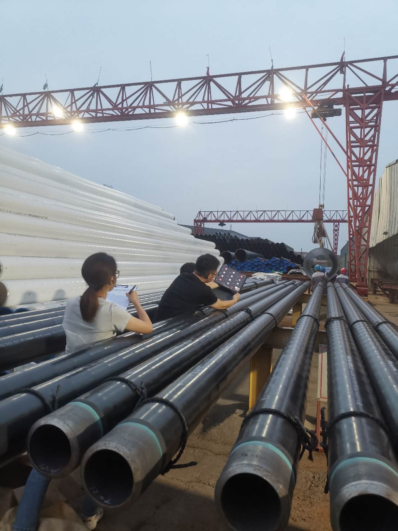 3LPE-coated line pipe staged in the ZC coating yard ahead of an Africa shipment. Getting the coating clauses right on the PO is what keeps stock like this compliant on arrival.
When procuring coated line pipe for sour service or offshore projects, specify:
Pipe: API 5L grade, PSL2, SR15C (HIC), OD, wall, quantity
External coating:
- System: FBE / 3LPE / 3LPP
- Thickness: per layer
- Standard: ISO 21809-1 or -2
- Cathodic disbondment: enhanced limit if sour service
- Holiday test: 100%
- Adhesion: minimum peel strength
Internal coating (if required):
- Type: FBE internal
- DFT: 200–400 µm
- Holiday test: 100%
- Temperature rating
CWC (if offshore):
- Density: kg/m³
- Thickness: mm
- Reinforcement specification
- Cutback: mm each end
- Standard: DNV-ST-F101
Documentation:
- MTC: EN 10204 3.2
- Third-party inspection scope
- Coating batch records and test reports
Procurement Trap — The Underspecified 3LPE PO
Wrong PO: "API 5L X65M PSL2 SR15C HIC, 10-inch × 9.53 mm, 3LPE external coating per ISO 21809-1, EN 10204 3.2."
What ships: The mill applies 3LPE to ISO 21809-1 standard default requirements — cathodic disbondment at the standard limit (15 mm at 65°C, not the tighter sour service limit); no peel adhesion enhancement; holiday test at the ISO minimum voltage for the coating thickness.
Correct PO additions: "3LPE minimum 3.0 mm; cathodic disbondment ≤ 8 mm radius at 65°C per ISO 21809-1; peel adhesion ≥ 150 N/cm at 23°C; holiday test at ISO 21809-1 Annex H voltage for actual specified thickness; NACE MR0175/ISO 15156 compliance for base pipe; MTC to include coating batch test reports."
Add separately as required: "Internal FBE 300 µm if water cut > 30%; high-temperature FBE grade if operating temperature > 70°C."
The cathodic disbondment limit is the critical PO clause. A mill receiving a PO with no CD limit will test to the ISO default (15 mm). A result of 14.9 mm at 65°C is a fully compliant shipment — and materially inadequate for a sour service pipeline in SRB-active soil. The 8 mm limit must be explicitly stated on the PO; it does not default from "ISO 21809-1" alone.
ZC Steel Pipe supplies the complete coated pipe package for sour service and offshore projects. Contact us with your project specification for a full supply proposal.
Frequently Asked Questions
What coating is required for sour service buried pipelines?
Sour service buried pipelines require external anti-corrosion coating combined with cathodic protection (CP) — the same combination used for sweet service pipelines. The coating specification difference for sour service is primarily in the pipe material (PSL2 + SR15C HIC tested) rather than the coating type. However, for buried sour service pipelines in wet H₂S environments, coating disbondment and cathodic protection shielding risk is higher, so coating adhesion requirements are more stringent. 3LPE with enhanced cathodic disbondment resistance, or FBE primer + 3LPE, are the standard external coating systems for buried sour service pipelines.
What is cathodic disbondment and why does it matter for sour service?
Cathodic disbondment is the loss of adhesion between the pipe coating and the steel surface caused by cathodic protection current passing through coating defects (holidays). The alkaline environment created by CP at coating defects degrades the coating adhesion over time, causing the coating to lift away from the steel. In sour service environments, disbonded coating creates a crevice where H₂S-saturated produced water can concentrate, significantly increasing the local corrosion and SSC risk. Coatings with good cathodic disbondment resistance — FBE and 3LPE — are preferred for sour service buried pipelines.
What external coating is standard for offshore subsea pipelines?
The standard external coating system for offshore subsea pipelines is FBE (300–500 µm) as the anti-corrosion primer, followed by concrete weight coating (CWC) for buoyancy control. For high-temperature flowlines (above 80°C), 3LPP replaces FBE as the anti-corrosion coating under CWC. For subsea pipelines without CWC requirement (risers, jumpers, spool pieces), 3LPP is often specified for its combination of temperature resistance and mechanical protection.
Does H₂S affect the external coating performance?
H₂S does not directly attack FBE, 3LPE, or 3LPP external coatings — these polymer coatings are chemically resistant to H₂S at the concentrations encountered externally on buried or subsea pipelines. The sour service challenge is in the pipe material, not the external coating. However, H₂S in the soil environment (from bacterial sulphate reduction) can accelerate external corrosion at coating defects where CP is insufficient, making good coating adhesion and CP design more critical for sour service environments.
What coating is required for offshore pipeline risers?
Offshore pipeline risers — the sections transitioning from the seabed to the platform or FPSO — require coatings that can withstand the splash zone (alternating wet and dry conditions with UV exposure and mechanical wave action) in addition to the submerged zone. Standard riser coating systems include: three-layer epoxy/polyurethane systems for the splash zone, 3LPP for the submerged section, and thermal insulation coating if flow assurance requires heat retention. The splash zone is the most aggressive coating environment and requires the most robust coating system.
What temperature rating is required for hot oil pipeline coatings?
Hot oil pipeline coatings must be rated above the maximum pipeline operating temperature including any upset conditions. For crude oil pipelines with operating temperatures of 60–80°C, 3LPE (rated to 80°C) is acceptable. For pipelines above 80°C — common in EOR (enhanced oil recovery), heavy oil, or high-temperature wellhead gathering — 3LPP (rated to 110°C, high-temp grade to 130°C) is required. FBE alone (rated to 95°C) can be used for moderate temperature buried pipelines but has lower mechanical protection than 3LPP.
How does coating selection affect cathodic protection design?
External pipeline coating and cathodic protection are designed together as a combined corrosion control system. Better coating (lower holiday rate, higher adhesion, better cathodic disbondment resistance) reduces the current demand on the CP system, allowing smaller sacrificial anodes (offshore) or lower impressed current output (onshore). FBE has the best cathodic disbondment resistance of the standard coating systems, followed by 3LPE. 3LPP has good cathodic disbondment resistance but requires careful field joint design to prevent CP shielding at field joints.
What coating is used for CO₂ injection pipelines?
CO₂ injection pipelines present an unusual corrosion challenge: dry supercritical CO₂ is non-corrosive to carbon steel, but CO₂ with even small amounts of water is extremely corrosive. External coating for buried CO₂ injection pipelines follows standard practice (3LPE or FBE + 3LPE). Internal protection depends on CO₂ quality specification — dry CO₂ (dew point controlled) uses bare carbon steel internally; wet CO₂ or uncertain quality requires CRA pipe or internal FBE coating with strict quality limits. The coating specification should be confirmed by the corrosion engineer based on CO₂ stream composition.