
Internal FBE coating serves two distinct purposes in line pipe systems: corrosion protection of the pipe bore from aggressive production fluids, and flow efficiency improvement through surface roughness reduction. These two functions are sometimes applied independently — flow efficiency internal FBE is common on sweet gas transmission pipelines where corrosion is not a concern, while corrosion-protective internal FBE is applied on liquid lines carrying produced water or CO₂-saturated fluids.
ZC Steel Pipe supplies line pipe with internal FBE coating applied at our coating facility, qualified to project specifications. Internal FBE is available for seamless and welded line pipe from 4-inch to 60-inch OD. This guide covers internal FBE specifications, application process, performance characteristics, and procurement requirements.
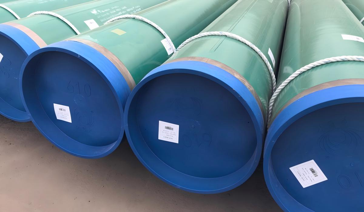 ZC pipe with green external FBE and a blue internal-FBE bore coating.
What we see on orders: On a produced water injection line in the Middle East, the project specified "internal FBE, 300 µm" without a temperature rating. The operating temperature was 85°C — 5°C above the standard FBE service limit of 80°C. The mill applied a standard-grade FBE product. The coating softened and delaminated within 8 months, causing pinhole corrosion at multiple locations on the injection line. Replacing the high-temperature FBE grade costs nothing extra at order time — the grade upgrade is a product selection, not a process change. Specifying "80°C" or "110°C continuous service" in the temperature rating line of the PO prevents this failure entirely.
1. Why Internal FBE Coating Is Specified
Internal FBE coating is specified for two distinct reasons:
Reason 1 — Corrosion protection: Carbon steel line pipe is susceptible to internal corrosion from produced water, CO₂ (sweet corrosion), H₂S (sour corrosion), and microbiologically influenced corrosion (MIC). Internal FBE provides a barrier between the pipe steel surface and the corrosive fluid. This is particularly important for:
- Oil and gas gathering lines with high water cut
- Produced water injection pipelines
- CO₂ injection lines
- Multiphase flow lines with intermittent water contact
Reason 2 — Flow efficiency: Even for non-corrosive gas pipelines, internal FBE coating reduces surface roughness from ~46 µm (bare steel) to ~5–10 µm (FBE coated). For long-distance high-volume gas transmission pipelines, this roughness reduction translates to measurable compression savings over the pipeline life.
| Benefit | Quantified Impact |
|---|---|
| Roughness reduction | 46 µm → 5–10 µm |
| Flow efficiency increase | 3–8% depending on flow velocity and pipe length |
| Compression cost reduction | 2–5% over pipeline life |
| Corrosion rate reduction | >90% reduction in corrosion rate vs uncoated |
The table above shows the headline numbers, but the two use cases have very different failure modes and procurement requirements. A gas pipeline specifying internal FBE purely for flow efficiency does not need a high-temperature grade or aggressive adhesion testing — the coating is not under corrosion attack. A produced water injection line specifying internal FBE for corrosion protection needs the full test battery: adhesion, holiday voltage, temperature rating, and pigging compatibility all stated on the PO.
2. Internal FBE Coating Specification
Standard specification parameters:
| Parameter | Typical Requirement |
|---|---|
| Coating type | Fusion bonded epoxy powder |
| Dry film thickness | 200–400 µm |
| Surface preparation | Sa 2.5 per ISO 8501-1 |
| Surface profile | 50–75 µm Rz |
| Application temperature | 180–240°C pipe preheat |
| Cure temperature | 200–240°C |
| Holiday test | 100% DC spark test |
| Holiday test voltage | 5 V/µm minimum |
| Adhesion | Minimum 14 MPa pull-off strength |
| Flexibility | No cracking at bend test |
| Max continuous temp | 80°C standard / 110°C high-temp grade |
| Reference standard | ISO 15741 / project specification |
The most commonly under-specified parameter in this table is the holiday test voltage. Many POs state "holiday test per NACE SP0188" without stating the voltage — and the voltage is where applicators have room to cut corners if it is not locked down.
For the underlying line pipe grade specifications, see the API 5L specification tables →. For grade selection on the base pipe, see the API 5L X65 line pipe specifications and the PSL1 vs PSL2 selection guide.
To verify the base pipe design pressure, use the Pipeline Design Calculator →
Holiday Test Voltage Calculation
Internal FBE holiday testing per NACE SP0188 uses a DC spark test at a voltage of 5 V per micrometre of specified dry film thickness. The calculation is straightforward, but the specified DFT — not the minimum DFT — must drive the test voltage. The table below shows the correct test voltage for the four most common DFT specifications:
| Application | Specified DFT | Calculation | Test Voltage |
|---|---|---|---|
| Gas pipeline, low corrosion risk | 250 µm | 5 × 250 | 1,250 V |
| Liquid pipeline, moderate risk | 300 µm | 5 × 300 | 1,500 V |
| Produced water injection | 400 µm | 5 × 400 | 2,000 V |
| Aggressive service | 500 µm | 5 × 500 | 2,500 V |
The test voltage must be stated on the PO using the specified DFT, not the minimum DFT. If the PO specifies "200–400 µm," the holiday voltage should be stated at 2,000 V (5 × 400 µm nominal) rather than allowing the coating applicator to use 1,000 V (5 × 200 µm minimum). An applicator defaulting to the minimum DFT test voltage will miss holidays in thicker sections of the applied coating — the spark cannot penetrate the full film thickness at the lower voltage.
3. Application Process
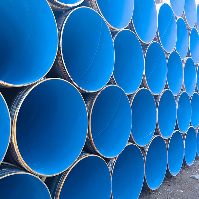 Finished internal FBE bore coating on stacked ZC line pipe.
Internal FBE coating requires specialised equipment and process control:
Step 1 — Surface preparation: The pipe bore is abrasive blast-cleaned using a centrifugal blast wheel or airless blast unit travelling through the pipe. Target cleanliness is Sa 2.5 per ISO 8501-1 with a surface profile of 50–75 µm Rz. Dust and abrasive are blown out and the surface temperature is checked to confirm it is above the dew point before coating.
Step 2 — Preheating: The pipe is heated to 180–240°C using a gas-fired oven, induction heating, or an internal infrared heating mandrel. Uniform temperature distribution is critical — hot spots cause early gelation and coating defects; cool spots result in incomplete cure.
Step 3 — FBE powder application: A rotating spray head travels through the pipe bore at a controlled speed, electrostatically applying FBE powder to the heated surface. The powder melts, flows, and begins to cure on contact. Spray head speed, rotation speed, and powder feed rate are controlled to achieve uniform thickness.
Step 4 — Cure: The pipe is maintained at cure temperature for the required time (typically 2–5 minutes at 200–220°C) to achieve full crosslinking of the epoxy. Incomplete cure reduces coating performance — chemical resistance and adhesion are both affected.
Step 5 — Inspection: After cooling, each pipe joint is inspected:
- DFT measurement by magnetic gauge — minimum 3 readings per joint
- Holiday test — 100% bore length DC spark test
- Visual inspection for runs, voids, or surface defects
4. Performance Characteristics
Chemical resistance: Internal FBE provides good resistance to:
- Crude oil and condensate
- Produced water with moderate salinity
- CO₂ at partial pressures up to approximately 0.5 MPa
- Mild H₂S at low concentrations
- Methanol and glycol injection
Limitations:
- Not suitable for strong acids (pH < 3)
- Not suitable for concentrated H₂S above NACE MR0175 / ISO 15156 limits
- Mechanical damage from pigging with aggressive pigs
- Temperature limit 80°C standard (110°C high-temp grade)
Pigging compatibility: Internal FBE-coated pipelines can be pigged using standard foam pigs and bi-directional pigs. Metal disc or brush pigs can damage the coating and should be used with caution. Specify pig type compatibility with the coating when designing the pigging programme.
Internal FBE is a physical barrier, not a corrosion inhibitor — it does not heal if damaged by pigging, debris, or weld root overhang. Once the coating is breached at any point, bare steel is exposed to the full corrosivity of the transported fluid at that location, often at a higher corrosion rate than uncoated pipe because the coating prevents chemical inhibitor contact with the steel. Design the pigging programme before specifying internal FBE, not after — the type of pigs used, the pig run frequency, and the expected debris load must all be reviewed against the coating's mechanical resistance before the coating is selected.
What we ship in FBE for crude oil lines: FBE is the coating we most associate with long-distance crude oil pipelines. On the East African Crude Oil Pipeline (EACOP) we supplied 18,000 tonnes of 24-inch API 5L X65M LSAW pipe with FBE coating. EACOP is a heated crude line, and FBE's high-temperature adhesion is exactly why it is specified there — the same bond-strength and temperature property that makes an internal FBE bore coating effective at protecting against the water and CO₂ carried in a warm crude stream.
5. Comparison — Internal FBE vs Chemical Inhibition
For pipelines with internal corrosion risk, the main alternatives are internal FBE coating and continuous chemical inhibitor injection:
| Factor | Internal FBE | Chemical Inhibition |
|---|---|---|
| Capital cost | Higher (one-time) | Lower |
| Operating cost | Minimal | Continuous (chemical + dosing system) |
| Corrosion protection | Passive — no ongoing action | Active — requires continuous injection |
| Field joint protection | Bare weld zones | Full coverage |
| Pipeline life | Coating life ~20–30 years | Ongoing as long as injected |
| Risk | Coating damage undetected | Under-dosing risk |
| Best for | Long-distance, high water cut | Short lines, low corrosion risk |
For long-distance pipelines with high water cut and significant internal corrosion risk, internal FBE coating typically provides better whole-life economics than continuous inhibitor injection. The comparison inverts for short pipeline sections — a 2 km gathering spur with moderate water cut is often better served by inhibitor injection, which covers the weld zones that FBE leaves bare and requires no specialist coating application.
6. Internal + External FBE — Dual Coating
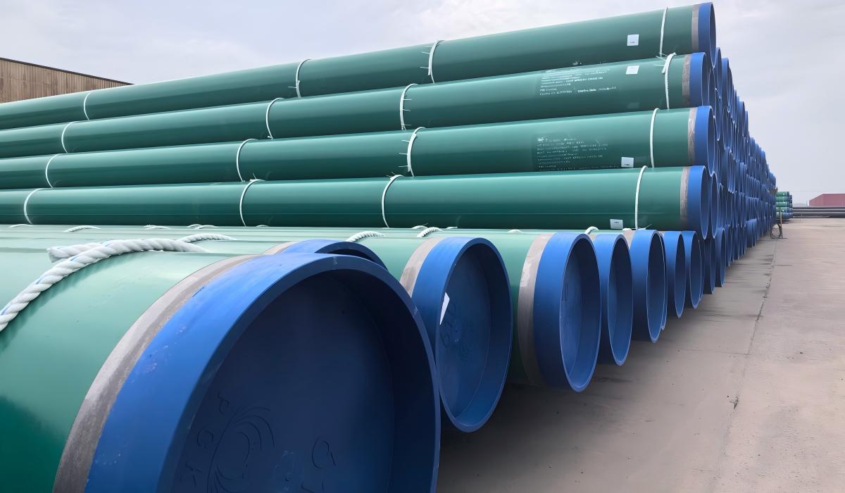 Dual-coated LSAW pipe stored in the yard, external FBE with blue internal-FBE bore ends.
Many offshore and onshore gas transmission pipelines use dual FBE coating:
Internal FBE: Flow efficiency coating 200–300 µm — reduces compression costs
External FBE: Anti-corrosion primer 300–500 µm — serves as the primer for concrete weight coating (CWC) offshore, or as standalone buried pipe coating onshore
Both coatings are applied in the same production run at the coating facility, with the pipe preheated once and internal and external powder applied sequentially. Dual FBE is a common specification for large-diameter offshore gas transmission pipelines. For the trade-off between FBE and the multi-layer 3LPE and 3LPP external systems, see the 3LPE vs FBE vs 3LPP coating selection guide.
7. Procurement Specification
When ordering line pipe with internal FBE coating, specify:
Pipe: API 5L grade, PSL, OD, wall, length, end finish
Internal coating:
- Type: Fusion bonded epoxy — internal
- DFT: [200–400] µm nominal, [175] µm minimum
- Surface preparation: Sa 2.5, [50–75] µm profile
- Holiday test: 100% at [5] V/µm
- Temperature rating: [80°C] or [110°C] high-temp
- Adhesion: minimum [14] MPa pull-off
- Reference standard: ISO 15741 / [project spec]
- MTC: EN 10204 3.2
- Third-party inspection: [SGS / BV / TÜV]
Cutback: Specify bare pipe length at each end for field joint welding — typically 100–150mm each end, or as specified by project pipeline engineer.
The Procurement Trap — What the Wrong PO Text Gets You
Wrong PO text: "API 5L X65M PSL2, 24-inch × 14.3 mm, internal FBE coating, 300 µm, ISO 15741."
What ships: The mill applies a standard-grade FBE product. The temperature rating is not specified, so the applicator uses their standard product rated to 80°C. No adhesion test criterion is stated, so the applicator does not run pull-off testing. The holiday test voltage defaults to the manufacturer's recommendation — often lower than the 5 V/µm NACE SP0188 requirement. No pigging compatibility requirement is stated, so no restriction on pig type is communicated. Every one of these gaps is a failure mode waiting to open in service.
Correct PO additions: "Internal FBE, 300 µm nominal DFT, 270 µm minimum; high-temperature grade rated 110°C continuous service; holiday test 100% bore at 1,500 V DC per NACE SP0188; adhesion minimum 14 MPa pull-off strength per ASTM D4541; compatible with foam and bi-directional pigs — metal disc and brush pigs excluded; MTC EN 10204 3.2 with DFT records per joint."
Adding these six parameters to the internal coating line of the PO takes approximately one minute and eliminates all of the failure modes described in the sections below. Each parameter corresponds to a real failure that has occurred on projects where it was omitted.
When NOT to Use Internal FBE
Internal FBE is the right coating for many liquid pipeline applications, but five specific service conditions make it the wrong choice — or require an upgrade to a different FBE grade before specifying it.
| Service condition | Alternative | Reason |
|---|---|---|
| Operating temperature > 80°C (standard grade) | High-temp FBE grade (110°C rating) or CRA liner | Standard FBE softens and delamines above 80°C |
| H₂S partial pressure > NACE MR0175 / ISO 15156 limits | CRA liner or inhibitor | FBE does not fully prevent SSC at high H₂S activity |
| Batch chemical treatment with strong solvents | Bare steel with inhibitor | Epoxy may be attacked by aromatic solvents in batch treatments |
| Short pipeline section where inhibitor injection is feasible | Chemical inhibitor | Inhibitor gives full bore coverage including weld zones; FBE leaves bare weld joints |
| Aggressive metal-disc pig programme already specified | Review pig selection first | Metal-disc pigs destroy internal FBE; coating is incompatible with this pig type |
The temperature row in this table is where projects most commonly get into trouble. The 80°C limit is a nominal continuous rating measured in a lab at steady state — it is not the practical service ceiling for a pipeline that cycles between ambient and operating temperature. Temperature cycling accelerates adhesion fatigue even below the nominal limit. For any application where maximum operating temperature exceeds 70°C, specify the high-temperature grade.
Internal FBE Failure Modes to Specify Against
Three failure modes account for the majority of premature internal FBE failures on liquid pipelines. Each one is preventable at the specification stage — none require any additional coating process change, only the correct PO language.
Failure Mode 1 — Undercure from insufficient preheat
Mechanism: Pipe preheat temperature drops below 180°C due to thermocouple calibration drift or uneven oven heating. FBE powder gels but does not fully crosslink. Undercured coating has adhesion below 14 MPa pull-off and reduced chemical resistance — the coating appears intact on visual inspection and passes holiday test but fails in service within 12–24 months as chemical attack degrades the adhesion layer.
Diagnostic: Adhesion test per ASTM D4541 on sample pipes reveals pull-off strength below 14 MPa. Solvent wipe test (MEK rub, 50 double rubs) shows softening or colour transfer on undercured areas. Both tests must be specified on the inspection plan as production release criteria — a holiday test alone will not detect undercure.
Fix: Calibrate thermocouple probes at pipe surface using a contact pyrometer before each production run. Require minimum preheat of 190°C measured at the pipe OD surface, not at the oven temperature setpoint. Include adhesion test on the first pipe of each production shift, with results verified before bulk production continues.
Failure Mode 2 — Mechanical disbonding at weld root overhang
Mechanism: Weld root bead overhang (internal weld reinforcement) creates a step in the pipe bore. FBE applied by a rotating spray head bridges the step rather than conforming into it, leaving an unbonded void at the weld root back face. Debris caught on the overhang during pigging impacts the bridged coating, creating a holiday at the weld zone — precisely the location where the pipe is already most corrosion-susceptible.
Diagnostic: ILI magnetic flux leakage (MFL) run shows corrosion features clustered within 50–100 mm of each weld seam on the pipe bore. The pattern identifies weld-root corrosion specifically, distinguishable from general pitting by its location distribution.
Fix: Specify maximum internal weld root protrusion height on the pipe PO — typically ≤ 1.5 mm per API 5L PSL2 for smooth bore. Request that the FBE applicator qualify the spray head speed and standoff distance at the weld root zone separately from the pipe body. Include weld zone in the DFT measurement programme so that bridged voids are detected before the pipe ships.
Failure Mode 3 — Temperature exceedance disbonding
Mechanism: Standard FBE grade applied to a pipeline where operating temperature episodically reaches 85–90°C during startup or hot crude delivery. Each temperature exceedance above 80°C thermally softens the FBE adhesion layer. Disbondment initiates at the weakest adhesion zones first — typically weld seams and any undercured patches from Failure Mode 1. Once disbonded, the loose FBE section acts as an internal flow restriction and traps corrosive fluid behind the delaminated sheet, accelerating corrosion at the bare steel underneath.
Diagnostic: ILI run shows widespread disbondment pattern uniformly distributed along the highest-temperature pipeline sections — near wellhead or pumping station outlets. The pattern is diffuse, not clustered at welds, distinguishing it from Failure Mode 2. Disbondment without holiday failures at the same locations confirms the coating has lifted rather than been punctured.
Fix: Specify high-temperature FBE grade (110°C continuous, 130°C peak) whenever maximum anticipated operating temperature exceeds 70°C — not 80°C. The 80°C ceiling is a nominal lab rating; the practical service limit with temperature cycling is lower. The grade upgrade is a product selection at order time, not a process change — it adds no lead time and negligible cost.
ZC Steel Pipe applies internal FBE coating to line pipe from 4-inch to 60-inch OD at our Hai'an City coating facility. Contact us with your OD, wall thickness, coating DFT, temperature requirement, and quantity for availability and lead time.
Frequently Asked Questions
What is internal FBE coating for line pipe?
Internal FBE (Fusion Bonded Epoxy) coating is a thermoset epoxy powder coating applied to the internal bore surface of line pipe to protect against internal corrosion and improve flow efficiency. The pipe bore is blast-cleaned to Sa 2.5, preheated, and FBE powder is electrostatically applied and cured inside the pipe. The result is a smooth, hard, chemically resistant coating typically 200–400 µm thick that significantly reduces corrosion from produced water, CO₂, and other corrosive species in the transported fluid.
What thickness is used for internal FBE coating?
Internal FBE coating for line pipe is typically applied at 200–400 µm dry film thickness (DFT). The standard thickness depends on the application: 200–250 µm for gas pipelines with low corrosion risk, 300–400 µm for liquid pipelines with higher corrosion potential. Some project specifications require thicker internal coatings (up to 500 µm) for aggressive service conditions. Thickness is measured by calibrated dry film thickness gauge on representative sample pipes from each batch.
What is the maximum operating temperature for internal FBE coating?
Standard internal FBE coating is rated for continuous operating temperatures up to 80°C and short-term peaks up to 95°C. For higher temperature applications, high-temperature FBE formulations are available with continuous ratings up to 110°C. Above 110°C, internal FBE coating is not suitable and alternative internal protection methods (CRA liner, inhibitor injection) should be evaluated. Always confirm the specific FBE product temperature rating against the maximum operating temperature including any transient conditions.
Does internal FBE coating improve flow efficiency?
Yes — internal FBE coating reduces the pipe bore roughness from the typical carbon steel value of approximately 46 µm (uncoated) to approximately 5–10 µm (FBE coated). This smooth surface reduces friction losses in the pipeline, increasing flow efficiency and reducing compression or pumping requirements. For long-distance gas transmission pipelines, the flow efficiency improvement from internal FBE coating can provide a meaningful reduction in compression costs over the pipeline life, partially offsetting the coating cost.
How is internal FBE coating applied to pipe?
Internal FBE coating is applied by: (1) abrasive blast cleaning the pipe bore to Sa 2.5 with a surface profile of 50–75 µm; (2) preheating the pipe to 180–240°C using an internal heating mandrel; (3) electrostatically applying FBE powder through a rotating spray head travelling through the pipe bore; (4) the powder melts on contact with the hot pipe surface, flows, and cures to form a continuous coating. The process requires specialised internal coating equipment and is typically done at a pipe coating facility rather than at the mill.
What happens at pipe field joints with internal FBE coating?
Internal FBE coating cannot be applied across field girth welds during pipeline installation — the weld zone is uncoated (bare steel) after welding. For gas pipelines, the short bare zone at field joints is typically acceptable as gas pipelines have low internal corrosion risk. For liquid pipelines with significant internal corrosion risk, liquid-applied epoxy field joint coating can be applied to the internal weld zone using long-reach application tools. The bare weld zone length is typically 100–150mm each side of the weld.
Can internal and external FBE coating be applied simultaneously?
Yes — dual-layer FBE coating (internal FBE + external FBE) can be applied in the same production run at some coating facilities. The pipe is preheated and FBE applied both internally and externally simultaneously or in sequence. Dual FBE coating is commonly specified for gas transmission pipelines where: external FBE serves as the primer for CWC (offshore) or as a standalone external coating for buried pipe, and internal FBE provides flow efficiency improvement and corrosion protection.
What standards govern internal FBE coating for line pipe?
Internal FBE coating for line pipe is governed by ISO 15741 (Paints and varnishes — Friction-reduction coatings for the interior of on- and offshore steel pipelines for non-corrosive gases) for flow efficiency coatings, and by project-specific specifications based on ISO 21809 principles for corrosion-protective internal coatings. NACE SP0185 and API RP 5L2 also provide guidance for internal coating of line pipe. Always confirm the applicable standard with the project specification.