
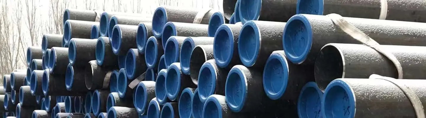
Offshore infield infrastructure faces a hard constraint: every girth weld in a subsea flowline is a potential failure point that requires inspection, testing, and qualified welders working in difficult conditions. For small-diameter lines connecting subsea wells to manifolds, or carrying control fluids inside umbilical bundles, the weld count adds installation time, cost, and risk in proportion to water depth. Coiled line pipe eliminates this problem by delivering the pipe in continuous coils that unroll directly from a reel-lay vessel, placing hundreds of metres of pipe without a single offshore butt weld. The benefit is real but not unconditional: winding a steel pipe onto a reel induces significant plastic strain, and that strain imposes metallurgical requirements — on grade, delivery condition, carbon equivalent, and coating — that must be designed into the procurement specification from the outset.
ZC Steel Pipe manufactures coiled line pipe in NPS 2 through NPS 6 (60.3 mm to 168.3 mm OD) to API Specification 5L, 46th Edition, PSL2, with M (thermomechanical) and Q (quench and temper) delivery conditions, serving offshore, subsea, and onshore clients across Southeast Asia, the Middle East, and West Africa.
At a Glance
Coiled line pipe is API 5L pipe supplied in continuous reels for reel-lay installation, which eliminates offshore girth welds on small-diameter subsea flowlines, umbilical carrier tubes, and tiebacks. It works only in smaller sizes — NPS 2 to NPS 6 (60.3–168.3 mm OD) — because winding the pipe onto a reel induces roughly 0.5–1.5% plastic strain that both the steel and its coating must survive. That strain is why the M (thermomechanical) delivery condition and a low carbon equivalent are not optional: specify "X65M (L450M)", never "X65".
| Attribute | Coiled line pipe |
|---|---|
| Standard | API 5L, 46th Edition, PSL2 |
| OD range | NPS 2–6 (60.3–168.3 mm) |
| Common grades | X52M, X60M, X65M |
| Delivery condition | M (TMCP) — mandatory for coilability |
| Coiling strain | ~0.5–1.5% (ε = OD / 2R) |
| Installation | Reel-lay, to ~3,000 m water depth |
| External coating | FBE or thin-film epoxy — never 3LPE/3LPP |
| Sour service | PSL2 + Annex H |
Derive size and design-pressure figures from the API 5L specification tables and the Pipeline Design Calculator. For a grounding in the parent product, see what line pipe is and how the standards fit together.
On a West Africa umbilical carrier tube order, the specification read "API 5L X65 PSL2" without an M suffix. The mill supplied X65 in the Q delivery condition — technically compliant with the PO as written. The Q steel had CE Pcm of 0.29, above the 0.25 limit required for reliable coilability. During coiling at the fabrication yard, the external FBE coating disbonded over approximately 35% of one coil's length as the higher-CE steel work-hardened unevenly. The entire 4.2-tonne coil was rejected. Emergency re-order of X65M added 12 weeks to the project schedule. One word — "M" — is the difference between a deliverable coil and a scrapped one.
What Is Coiled Line Pipe?
Coiled line pipe is steel pipe produced to API Specification 5L, 46th Edition, and supplied wound into large continuous coils rather than cut into the standard 12-metre random-length joints used for most onshore and platform pipelines. Because the pipe must bend plastically around a reel or mandrel at the fabrication yard and again straighten over the stinger of the installation vessel, only smaller diameters are practical. The standard commercial range is NPS 2 (60.3 mm OD) through NPS 6 (168.3 mm OD), with wall thicknesses of approximately 4.0 mm to 12.7 mm depending on OD, pressure rating, and service classification.
Both electric resistance welded (ERW) and seamless manufacturing routes are used — the tradeoffs between them are set out in the seamless vs welded line pipe selection guide. ERW dominates for NPS 2 through NPS 4, where the continuous strip-to-pipe process integrates naturally with coiling and produces a consistent wall at high volume. Seamless pipe is specified for critical-service applications — high-pressure, high-temperature, or sour — where weld zone properties are a concern. Individual coils can reach 50 tonnes in weight for large-vessel reel systems, providing uninterrupted pipe lengths of several kilometres from a single coil.
The term coiled line pipe is sometimes confused with coiled tubing (CT). They are unrelated products. Coiled tubing is a downhole intervention tool, typically 25 mm to 89 mm (1 to 3.5 inches) in diameter, designed for thousands of bending cycles and governed by its own proprietary standards. Coiled line pipe is a permanent pipeline product governed by API 5L and designed for a defined number of plastic strain cycles — typically one coiling cycle plus one installation cycle — not continuous cyclic fatigue.
Coiling Strain: Why Metallurgy Matters
When pipe is wound onto a reel, the outer wall goes into tension and the inner wall into compression. For a pipe that remains elastic this creates no permanent change. At the diameters and reel sizes used in offshore installation, however, the strain exceeds the material's elastic limit and the pipe deforms plastically. This plastic strain must be within the material's capacity, or the pipe will crack, buckle, or lose its pressure-bearing integrity.
Coiling Strain — Step-by-Step Calculation
For a 114.3 mm (NPS 4) pipe coiled on a reel with 7.5 m radius:
Step 1 — Identify pipe OD and reel radius: OD = 0.1143 m, R = 7.5 m
Step 2 — Apply the outer-fiber coiling strain formula: ε = OD / (2R) = 0.1143 / (2 × 7.5) = 0.1143 / 15.0 = 0.00762 = 0.76%
Step 3 — Compare to material limit: API 5L PSL2 X65M minimum elongation = 18% in 2 inches. Coiling strain of 0.76% is well within elongation capacity for the full coiling cycle. However: the Bauschinger reverse strain during straightening reduces the effective post-straightening yield strength. DNV-ST-F101 requires this reduced yield to be used in MAOP design calculations — not the original mill cert value.
Step 4 — Check for NPS 6: OD = 0.1683 m, same reel R = 7.5 m ε = 0.1683 / 15.0 = 0.01122 = 1.12% Higher strain for the larger OD — requires tighter material qualification and coating validation. Confirm with coating supplier that FBE formulation can sustain 1.1%+ bending strain.
Typical coiling strains for the commercial NPS 2–6 range, on reels of 5 m to 10 m radius, typically fall between 0.5% and 1.5%. These are substantial plastic strains by the standards of pipeline design, where hoop stress design codes such as ASME B31.8 treat the pipe as elastic. The material must sustain them without cracking, without significant toughness reduction, and without leaving the pipe in a condition that impairs its in-service performance.
This is why the thermomechanical controlled processing (TMCP) delivery condition — designated by the M suffix in API 5L — is the standard choice for coiled line pipe. TMCP steels achieve their strength through controlled rolling and accelerated cooling rather than through high carbon or large alloy additions. The result is a lower carbon equivalent (CE Pcm) than quench-and-temper or normalised steels at the same strength grade, better Charpy toughness at low temperature, and improved resistance to hydrogen-induced cracking under sour conditions. All of these properties matter more when the pipe has been cold-worked by coiling.
A secondary effect that procurement engineers must account for is the Bauschinger effect. When a steel pipe is coiled in one direction and then straightened in the opposite direction, the reverse plastic straining temporarily reduces the apparent yield strength. This reduction is real and must be included in the design pressure calculations for the installed pipeline. DNV-ST-F101 Submarine Pipeline Systems provides the framework for evaluating this effect and for setting the acceptance criteria on accumulated plastic strain.
The Bauschinger effect is not a theoretical adjustment — it is a real reduction in the yield strength that governs the installed pipeline's MAOP. When pipe is coiled (strained in one direction) and then straightened (strained in reverse), the effective yield strength in the pipe axis can drop 15–25% compared to the original mill certificate value. This reduced yield is what must be used in the ASME B31.8 or DNV-ST-F101 design pressure calculation for the installed line, not the mill cert value. Procurement engineers who calculate MAOP from the mill cert and do not apply a post-coiling yield reduction may find their installed pipeline is operating closer to the design limit than the calculations suggest.
API 5L Grades for Coiled Line Pipe
Three PSL2 grades with M delivery condition cover the practical range of coiled line pipe projects: X52M, X60M, and X65M.
Chemistry Requirements (PSL2, M Delivery Condition)
| Grade | C max (%) | Si max (%) | Mn max (%) | P max (%) | S max (%) | Nb+V+Ti max (%) | CE IIW max | CE Pcm max |
|---|---|---|---|---|---|---|---|---|
| X52M (L360M) | 0.22 | — | 1.40 | 0.025 | 0.015 | — | 0.43 | 0.25 |
| X60M (L415M) | 0.12 | 0.45 | 1.60 | 0.025 | 0.015 | 0.15 | 0.43 | 0.25 |
| X65M (L450M) | 0.12 | 0.45 | 1.60 | 0.025 | 0.015 | 0.15 | 0.43 | 0.25 |
The low carbon maxima of 0.12% for X60M and X65M directly support coilability. Lower carbon reduces the martensite-start temperature and limits the formation of hard phases at the weld line in ERW pipe, both of which contribute to crack resistance under plastic bending. CE Pcm max of 0.25 for all three grades reflects API 5L PSL2 requirements and is the carbon equivalent formulation most relevant for low-carbon TMCP steels.
Tensile Requirements (PSL2)
| Grade | Min Yield (MPa) | Max Yield (MPa) | Min Tensile (MPa) | Max Tensile (MPa) | Max Y/T |
|---|---|---|---|---|---|
| X52 PSL2 | 360 | 530 | 460 | 760 | 0.93 |
| X60 PSL2 | 415 | 565 | 520 | 760 | 0.93 |
| X65 PSL2 | 450 | 600 | 535 | 760 | 0.93 |
The maximum yield-to-tensile ratio of 0.93 is a PSL2 requirement that limits strain hardening capacity. For coiled pipe, a lower Y/T ratio in the as-coiled condition provides more plastic reserve before fracture. Post-coiling tensile testing should confirm that the Bauschinger softening has not pushed the yield strength below the minimum specified value.
PSL2 also mandates Charpy V-notch impact testing. The test temperature is project-specific and should reflect the minimum installation temperature and the minimum design temperature of the installed pipeline. For West African deepwater at 1,000 m water depth, seabed temperature is approximately 4°C; many operators specify Charpy testing at 0°C or −10°C.
Sour Service: Annex H
For coiled line pipe that will carry wet sour gas or sour produced water — defined by NACE MR0175 / ISO 15156 as fluids with partial pressure of H₂S above 0.0003 MPa (0.05 psia) in the gas phase — PSL2 alone is insufficient. The pipe must additionally meet API 5L PSL2 Annex H, which imposes:
- Tighter sulfur maximum (0.003%)
- Tighter phosphorus limits
- HIC resistance testing per NACE TM0284, with maximum crack length ratio (CLR), crack thickness ratio (CTR), and crack sensitivity ratio (CSR) limits
- Lower maximum hardness
Annex H sulfur and HIC acceptance limits should be verified against the current edition of API Specification 5L before specifying. The 0.003% sulfur limit and HIC criteria stated here reflect the 46th Edition as of 2026.
X52M and X60M in PSL2 Annex H condition are the workhorses for sour-service coiled flowlines. X65M sour is achievable but demands tighter process control and may require supplier qualification testing before purchase order placement.
Standard Sizes: OD, Wall, and Weight
The table below covers the principal coiled line pipe sizes in commercial supply. Wall thickness ranges reflect the combination of pressure requirements and coilability limits; thicker walls at a given OD reduce coiling strain slightly (because D/t decreases) but increase the bending moment required and the coil weight per unit length.
| NPS | OD (in) | OD (mm) | Common Wall (mm) | Common Grade |
|---|---|---|---|---|
| 2 | 2.375 | 60.3 | 4.8–7.1 | X52M / X60M |
| 2½ | 2.875 | 73.0 | 5.2–7.6 | X52M / X60M |
| 3 | 3.500 | 88.9 | 5.5–8.1 | X52M / X60M |
| 4 | 4.500 | 114.3 | 6.0–9.5 | X60M / X65M |
| 6 | 6.625 | 168.3 | 7.1–12.7 | X65M |
ZC Steel Pipe supplies all sizes in the table above in both ERW and seamless form. For sour-service applications, wall thickness is verified against the maximum allowable operating pressure (MAOP) calculated per ASME B31.8 or DNV-ST-F101, with the corrosion allowance and fabrication tolerance included in the wall selection, not treated as contingency.
NPS 2 and NPS 2½ in X52M are the dominant sizes for umbilical carrier tubes and chemical injection lines. NPS 4 in X60M or X65M is the standard for infield flowlines connecting subsea wells to production manifolds at water depths up to approximately 1,500 m. NPS 6 in X65M is used for larger-throughput tieback lines and for reeled pipe-in-pipe systems where the NPS 6 pipe serves as the inner carrier.
For the complete PSL1 and PSL2 grade tables, see the API 5L specification tables → and the ASME B36.10M pipe schedule chart →
To calculate design pressure or minimum wall thickness for your pipeline, use the Pipeline Design Calculator →
Offshore Applications
Infield Flowlines
The most common application for coiled line pipe offshore is the infield flowline: the short pipeline connecting a subsea wellhead or Christmas tree to the production manifold. Lengths typically range from a few hundred metres to three kilometres. Each connection in a conventional joint-pipe system would require two to four girth welds per joint, each of which must be inspected by automated ultrasonic testing (AUT) or radiography in a challenging subsea environment. A single coil of NPS 4 line pipe can eliminate twenty to forty welds from a typical tieback, reducing both schedule and inspection cost substantially.
Deepwater Tiebacks
As water depth increases, the time-on-bottom for welded joint installation increases and the cost of weld repair escalates. At depths beyond 500 m, reel-lay with coiled line pipe becomes economically preferable to S-lay for lines up to NPS 6. Modern reel-lay vessels operate in water depths to approximately 3,000 m with NPS 4–6 coiled pipe, laying at speeds of 1–3 km per day compared to 200–500 m per day for S-lay in equivalent conditions.
Umbilical Carrier Tubes
Subsea umbilicals bundle hydraulic hoses, electrical cables, and small-bore steel tubes into a single armoured structure. The steel tubes — NPS 2 and NPS 3 coiled line pipe — carry hydraulic fluid for wellhead control systems and chemical injection fluids (methanol, scale inhibitor, corrosion inhibitor). These tubes must survive the coiling of the umbilical during fabrication and the laying tension during installation. API 5L X52M or X60M PSL2 is standard for this service; where the injection fluid is sour, Annex H is mandatory.
Reeled Pipe-in-Pipe
Pipe-in-pipe (PiP) systems use an outer sleeve to provide thermal insulation for the inner carrier pipe, preventing wax deposition and hydrate formation in deepwater flowlines. When the inner carrier is NPS 4 or NPS 6 coiled line pipe and the outer sleeve is a larger-diameter pipe, the entire assembly can be reeled onto an installation vessel and laid in a single pass. This is the reeled PiP method. The inner pipe is the structural and pressure-containing element and must meet all API 5L PSL2 requirements; the outer sleeve is typically a lower-specification structural pipe.
Onshore Applications
Outside the offshore sector, coiled line pipe serves a niche but valuable role in onshore processing facilities. Short infield connections between separators, headers, and injection pumps can be made with coiled pipe to avoid field welding in congested areas or in classified zones where hot work permits are difficult to obtain. Temporary bypass lines during plant maintenance are another common use, where the coil can be redeployed after the outage.
When NOT to Use Coiled Line Pipe
| Scenario | Risk | Correct Approach |
|---|---|---|
| OD above NPS 6 (168.3 mm) | Coiling radius required becomes impractical for standard reel systems; excessive coiling strain | Use conventional joint pipe with S-lay or J-lay for OD > NPS 6 |
| Sour service without Annex H | Standard PSL2 sulfur (0.015%) allows MnS inclusions that trap atomic hydrogen → HIC | Specify PSL2 Annex H explicitly: S ≤ 0.003%, calcium treatment, HIC testing per NACE TM0284 |
| 3LPE or 3LPP external coating | Thick polymer layer cracks under bending strain during coiling and reel-lay | Use external FBE (typically 400–500 µm) or strain-compatible thin-film liquid epoxy validated to coiling radius |
| Q or N delivery condition | Higher CE than M delivery; greater risk of HAZ hardening at ERW weld and coating disbondment under coiling strain | Always specify M (TMCP) delivery condition explicitly on the PO — write "X65M (L450M)" not "X65" |
| Charpy temperature not specified | API 5L default Charpy test at 0°C may not cover the minimum seabed or installation temperature | Specify CVN test temperature equal to the minimum design temperature; for deepwater, typically 0°C to −10°C |
| Multiple coil welds (lap joints) to extend length | Weld zones in a continuous coil create stress concentrations under coiling strain; weld quality must be rigorously controlled | Require full-penetration butt welds between coil sections with 100% RT or AUT and flatten/bend testing |
Installation Methods
Reel-Lay
Reel-lay is the installation method for which coiled line pipe is designed. The coil is loaded onto the reel of a specialist vessel at a fabrication yard or load-out facility onshore. Offshore, the vessel positions over the pipeline route and pays out the pipe over a curved stinger that controls the departure angle into the water. The pipe is straightened by aligner rollers as it passes off the reel, then curves again over the stinger before hanging in catenary to the seabed.
The plastic strain cycle the pipe experiences is: coiling at the fabrication yard (one direction) → transport on reel → uncoiling and straightening over the aligner (reverse direction) → bending over the stinger (one direction) → elastic catenary hang → laying onto seabed. Each bending event contributes to the accumulated plastic strain. DNV-ST-F101 (current edition) governs the strain acceptance criteria and requires the total accumulated plastic strain to remain below the material's elongation limit with an appropriate safety factor.
J-Lay Variant
For ultra-deepwater, some reel-lay vessels use a J-lay configuration where the pipe departs the vessel nearly vertically. The plastic strain cycle is similar; the primary difference is the catenary geometry and the resulting lay tension, which influences wall thickness design.
External Coating Survival During Installation
External coatings must survive the reel-lay plastic strain cycle without disbonding or cracking. The stresses at the outer surface during coiling can exceed 1% strain locally. Thick polymer coatings — three-layer polyethylene (3LPE) at 3–5 mm thickness — cannot sustain this strain without micro-cracking, which then allows seawater ingress and underfilm corrosion. This is why 3LPE is not used for coiled line pipe. External FBE at controlled thickness (typically 400–500 µm) and thin-film liquid epoxy systems with proven strain compatibility are the standard external protection for coiled pipe.
Coated Coiled Line Pipe
Internal Coating
Internal fusion-bonded epoxy (FBE) is the preferred internal lining for coiled line pipe, applied by the powder-spray electrostatic process before coiling. A properly formulated internal FBE at 300–500 µm dry film thickness can sustain approximately 0.5% bending strain without cracking, which is within the range of NPS 2–3 applications on standard reels. For NPS 4–6 where strains may reach 0.75–1.0%, the FBE formulation and application thickness must be validated by bend testing on representative specimens before bulk application.
Internal coating serves two purposes for coiled line pipe: corrosion protection during the operational life of the flowline, and flow efficiency improvement by reducing pipe wall roughness. For chemical injection lines, internal coating also prevents contamination of the injection chemical by corrosion products.
External Coating
External coating for coiled line pipe is constrained by the strain requirement. The options in current commercial use are:
- External FBE at reduced thickness (300–500 µm): The same chemistry as internal FBE but applied externally. Survives coiling strain if film thickness is controlled and the pipe surface preparation meets Sa 2.5.
- Thin-film liquid epoxy: Two-component solvent-free or low-solvent epoxy at 200–500 µm, applied after FBE or as a standalone coating. Must be strain-tested to the specific coiling radius.
- 3LPE or 3LPP: Not recommended for coiled pipe. The polyethylene or polypropylene topcoat is too stiff to bend plastically without cracking at the strains involved in reel-lay.
For full coating system selection guidance, including sour service, deepwater, and high-temperature applications, see the pipeline coating selection guide for sour service and offshore environments.
Procurement Traps
Procurement trap 1 — M suffix omitted:
Wrong PO: "API 5L X65 PSL2, 114.3 mm × 8.0 mm, coiled line pipe."
What ships: X65Q (quench and tempered) or X65N (normalised) — fully API 5L compliant, but with C max 0.18% vs 0.12% for X65M, and CE Pcm potentially 0.27–0.29 vs the 0.25 maximum for X65M. This steel is more brittle under coiling strain and the higher CE leads to harder ERW weld zones — both increasing the risk of coating disbondment and weld zone cracking during coiling.
Correct PO: "API Specification 5L, 46th Edition, PSL2, Grade X65M (L450M), TMCP delivery condition, 114.3 mm × 8.0 mm, coiled supply. CE Pcm ≤ 0.25 to be verified on MTC."
Procurement trap 2 — CE IIW only, not CE Pcm:
For low-carbon TMCP steels such as X60M and X65M, CE Pcm (= C + Si/30 + (Mn+Cu+Cr)/20 + Ni/60 + Mo/15 + V/10 + 5B) is the more sensitive indicator of weldability and cold cracking susceptibility than CE IIW. Request CE Pcm on every MTC for coiled line pipe; CE IIW alone is insufficient.
Procurement trap 3 — No bend test on coated pipe:
Ordering coated coiled pipe without specifying a bend test of the applied coating before shipment risks discovering adhesion failures after the pipe is wound. Require a bend test to the specified coiling radius on at least one coated sample per heat before bulk acceptance.
Failure Modes
Failure Mode 1 — Q delivery pipe fails coating during coiling
Mechanism: X65Q is specified but the M suffix is omitted from the PO. The mill supplies Q&T pipe with CE Pcm of 0.29. During cold coiling at the fabrication yard, the higher-CE steel work-hardens less uniformly than TMCP steel, creating localised surface strain concentrations. The FBE coating disbonds over multiple areas of the coil where local strain peaked. The disbonded areas cannot be repaired in situ — the entire coil must be scrapped.
Diagnostic: Coating holiday test after coiling reveals large areas of disbondment. Metallurgical review of the MTC confirms delivery condition Q, not M. CE Pcm on the MTC is 0.29 versus the 0.25 typically achieved by X65M. The PO contained no delivery condition specification — only "API 5L X65 PSL2."
Fix: All coiled line pipe POs must explicitly state the M delivery condition and CE Pcm ≤ 0.25. Add a hold point at the mill for CE verification before coiling commences.
Failure Mode 2 — 3LPE applied to coiled pipe disbonds at first bend
Mechanism: A project specifies 3LPE external coating for corrosion protection of a subsea flowline, not realising that 3LPE (3–5 mm thick) cannot sustain the bending strain of coiling. At the coil OD, the outer surface of the polyethylene topcoat experiences approximately 1% tensile strain. The PE layer micro-cracks at this strain, creating a disbondment path. Seawater enters the disbonded zone during reel-lay, leading to underfilm corrosion that is not detectable until the next inspection interval.
Diagnostic: Post-lay inspection (inline inspection or cathodic protection current demand monitoring) reveals a large area of active corrosion at a predictable location on the flowline. Disbondment pattern matches the coil geometry — confirming the failure mode is PE cracking under bending, not manufacturing defect or in-service damage.
Fix: For coiled line pipe, specify external FBE (400–500 µm) or strain-compatible thin-film liquid epoxy validated to the project coiling radius. Include a coating bend test in the qualification programme before production coating commences. Never specify 3LPE or 3LPP for coiled pipe.
Failure Mode 3 — Charpy not specified; pipe fails at cold seabed temperature
Mechanism: Coiled line pipe is ordered to API 5L PSL2 with no Charpy temperature specified. The mill tests at 0°C — the API default. The flowline is installed in 1,200 m water depth where seabed temperature is −1°C to 2°C year-round. During a hydrostatic test after installation, a weld zone fractures at a Charpy energy consistent with 0°C testing but insufficient for −5°C. The API test at 0°C showed adequate toughness; at the actual seabed temperature, the material was at its ductile-to-brittle transition.
Diagnostic: Failure occurs at a weld zone during hydrostatic testing. Fracture appearance shows cleavage fracture consistent with brittle failure. Charpy testing of weld metal at −5°C confirms energy below the minimum for the wall thickness per DNV-ST-F101.
Fix: Always specify Charpy test temperature equal to or below the minimum design temperature, not the API 5L default. For deepwater applications, determine the minimum seabed temperature from oceanographic data and subtract a margin (typically 5°C) for conservatism. Write the Charpy requirement explicitly in the PO.
Purchase Order Guidance
Specifying coiled line pipe requires more detail on the purchase order than standard joint pipe, because the coiling parameters interact with the material specification in ways that affect suitability. The following checklist covers the critical items.
PO Specification Checklist
- Standard: API Specification 5L, 46th Edition, PSL2
- Grade and delivery condition: State the full grade designation — for example, X65M (L450M). Do not write "API 5L X65" without the M suffix.
- OD and wall: State in millimetres, not NPS designation, for international procurement — e.g., 114.3 mm × 8.0 mm.
- Coil OD and ID: Specify the maximum coil outside diameter and minimum inside diameter (mandrel size). These determine the minimum reel radius and therefore the coiling strain the pipe must sustain.
- Maximum coil weight: Match to the handling capacity of the fabrication yard and installation vessel.
- Charpy test temperature: Specify in °C based on the minimum design temperature. Do not leave this blank.
- Sour service: If required, add "PSL2 Annex H" to the grade designation and specify HIC test solution and acceptance criteria per NACE TM0284.
- Internal coating: State type, dry film thickness, and holiday test voltage.
- External coating: State type, dry film thickness, and strain test requirement.
- Mill test certificates: Request CE Pcm (not only CE IIW), full chemistry, tensile results, Charpy results, and HIC test results if Annex H.
ZC Steel Pipe's technical team provides procurement specification review for coiled line pipe projects, including coiling strain calculations, coating compatibility assessment, and Annex H suitability analysis, before order placement.
Frequently Asked Questions
What is coiled line pipe?
Coiled line pipe is steel pipe manufactured to API Specification 5L and supplied in continuous coils rather than discrete joints. It is produced in smaller diameters — typically NPS 2 through NPS 6 (60.3 mm to 168.3 mm) — and is used primarily for offshore infield flowlines, umbilical carrier tubes, and deepwater tieback spools where continuous-coil delivery reduces installation time and eliminates field girth welds.
What API 5L grades are used for coiled line pipe?
Coiled line pipe is most commonly supplied in API 5L X52, X60, and X65, all PSL2, with the M (thermomechanical) delivery condition preferred because the lower carbon and carbon equivalent of TMCP steel supports the plastic strain during coiling without cracking. Higher grades such as X70 are technically possible but require tighter strain analysis.
What is the maximum OD for coiled line pipe?
The practical OD limit for coiled line pipe is approximately NPS 6 (168.3 mm OD) for reel-lay vessels, though most coiled products are NPS 4 (114.3 mm) and below. Above NPS 6, the coiling radius required to maintain acceptable plastic strain becomes impractical for standard reel systems, and conventional joint pipe with S-lay or J-lay is used instead.
How is coiling strain calculated for line pipe?
Coiling strain is the outer-fiber bending strain induced when pipe is wound onto a reel or mandrel. It is calculated as ε = OD / (2R), where OD is the pipe outside diameter and R is the reel radius. For a 114.3 mm pipe on a 7.5 m radius reel, strain equals approximately 0.76%. API 5L PSL2 and DNV-ST-F101 require the material to sustain this strain without cracking, driving the selection of TMCP steels with low carbon equivalent.
What is the difference between coiled line pipe and coiled tubing?
Coiled tubing (CT) is a downhole intervention tool used to convey tools and fluids inside a wellbore. It is typically small-diameter (1 to 3.5 inches), made from high-cycle-fatigue steel, and spooled on CT units. Coiled line pipe is a surface or subsea pipeline product, produced to API 5L, and used as a permanent flow conduit. The two products are governed by different standards and serve entirely different functions.
Does coiled line pipe require special coating?
Yes. The most common coating for coiled line pipe is internal FBE applied before coiling, with external FBE or thin-film liquid epoxy that can withstand the plastic strain of coiling without disbonding. Three-layer polyethylene (3LPE) is generally not used for coiled pipe because the thick outer layer cracks under bending strain. Coating selection must be validated for the specific coiling radius and operating temperature.
What installation method is used for coiled line pipe offshore?
Coiled line pipe is installed by reel-lay vessels, which unwind the pipe from a large horizontal or vertical reel over a stinger into the sea. The reel-lay method is faster than S-lay for small-diameter lines because it eliminates offshore welding. The pipe undergoes plastic straining during the reeling, unreeling, and straightening cycle, which must be accounted for in material selection and fatigue design per DNV-ST-F101.
Can coiled line pipe carry sour service fluids?
Yes, with proper grade and delivery condition selection. For sour service, coiled line pipe must meet API 5L PSL2 Annex H (formerly Annex B) requirements, which impose lower carbon equivalent, tighter sulfur and phosphorus limits, and HIC resistance testing. X52M and X60M PSL2 Annex H grades are the most common choices for sour-service coiled flowlines.