
External pipeline corrosion prevention requires two complementary systems working in tandem: a barrier coating that physically isolates the pipe surface from corrosive soil or seawater, and cathodic protection (CP) that electrochemically suppresses corrosion at locations where the coating is absent or has failed. Neither system is adequate on its own. A buried pipeline with only a coating will eventually corrode at holidays and weld seams. A buried pipeline with only CP will corrode slowly even under full protection potential — at a rate determined by the soil resistivity and the current demand across the entire bare pipe surface. The combination of a high-quality external coating that minimizes bare area and a properly designed CP system that protects residual holidays is the basis for all modern long-distance pipeline corrosion control programs.
ZC Steel Pipe supplies coated line pipe for buried and offshore applications, including 3LPE, FBE, and 3LPP external coating systems with mill-applied coating and field joint kit supply for EPC projects in Africa, the Middle East, South America, and Southeast Asia. PSL-2 line pipe with EN 10204 3.1 MTC and third-party coating inspection is available for all coating systems. Where internal corrosion control is also required, we supply internal FBE-lined pipe on the same order.
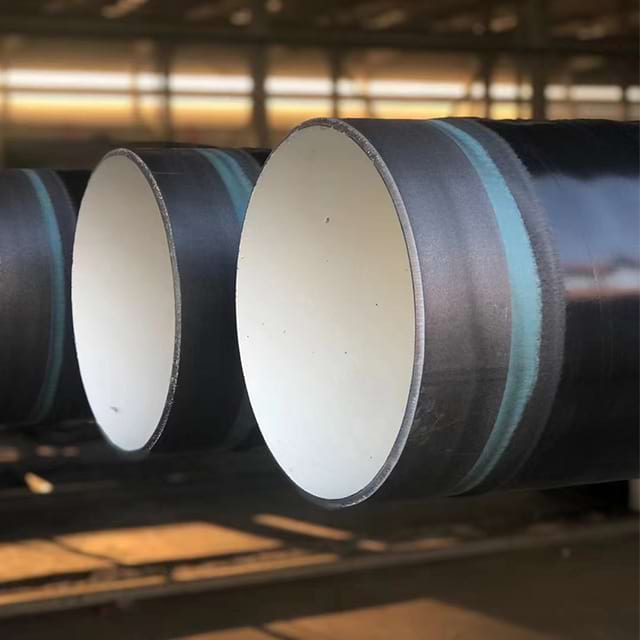 Three-layer coated line pipe with the black polyethylene topcoat over the FBE undercoat — the barrier layer that reduces the bare steel area cathodic protection must then defend.
Quick Answer
A coating and cathodic protection (CP) work as one system: the coating minimizes the bare steel area, and CP suppresses corrosion at the residual holidays and disbonded zones the coating cannot prevent. Two rules drive the design — hold the pipe-to-soil potential inside the protection window, and size the CP system for the end-of-life coating condition, not the pristine commissioning state.
| Design parameter | Value (per NACE SP0169) |
|---|---|
| Minimum protection potential | −850 mV CSE |
| SRB / high-temperature soils | −950 mV CSE |
| Overprotection limit (X70/X80) | −1,100 mV CSE |
| CP current sizing basis | End-of-life coating — roughly 3–10× commissioning demand |
What we see on projects: On a 350-km buried gas pipeline in East Africa, the CP system was sized to deliver −850 mV CSE at commissioning. The coating specification said "3LPE per ISO 21809-1" with no end-of-life current density requirement stated on the design basis. After 8 years in a laterite soil environment with moderate SRB activity, coating holiday rate had increased approximately 5× from commissioning — typical for polyethylene coatings in this soil type. The rectifiers were already at maximum output and could not maintain protection potential at −850 mV CSE. Six pipe segments showed active corrosion at coating holidays. Rectifier station upgrades cost USD 120,000 each; four additional stations were required. Specifying CP current demand at end-of-life (30 years), not at commissioning, is a fundamental design requirement of NACE SP0169 — and it must appear explicitly on the CP design basis document attached to the pipe coating PO.
Why Coatings Alone Are Not Enough
Pipeline coatings are applied to near-perfect steel surfaces under controlled shop conditions, but no coating system achieves zero defect rate at installation. Even a well-applied 3LPE coating at 4.5 mm total thickness will have some residual holidays from:
- Pinholes or thin spots in the FBE undercoat
- Damaged polyethylene topcoat from stacking, handling, and transport to site
- Field joint coating defects at each pipe girth weld
- Mechanical damage from rocks during backfilling
The residual bare steel area after installation is typically less than 0.1% of the total pipe surface for a well-applied shop coat, but this small exposed area is electrochemically active and will corrode at a rate determined by the local soil chemistry and moisture content. Without CP, even 0.1% bare steel corrodes at a rate that can penetrate a pipeline wall in years to decades, depending on soil corrosivity and the concentration of aggressive species.
Beyond installation defects, coatings degrade across the 30–40 year design life of a pipeline. Soil movement, thermal cycling, and UV exposure at above-grade sections reduce adhesion and create new holidays. CP is therefore required not just at commissioning but for the full life of the pipeline, and the CP design current capacity must account for the degraded coating condition at end of life, not just the pristine condition at startup.
Types of Cathodic Protection: ICCP and SACP
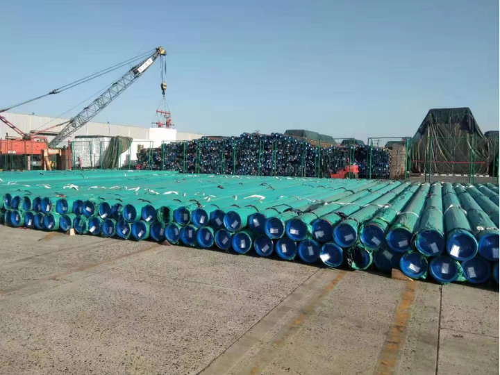 Coated line pipe staged under tarps in the yard — this consignment was X65 with a 3LPE external coating system.
Impressed Current Cathodic Protection (ICCP)
ICCP uses a rectifier connected to a DC power source — mains electricity or solar — to impress a direct current through the soil to the pipeline. The pipeline is connected to the negative terminal (cathode), and inert or semi-consumed anodes (high-silicon cast iron, mixed metal oxide, or graphite) are buried adjacent to the pipeline in soil, in a carbonaceous backfill that reduces the anode-to-soil resistance.
Key ICCP design parameters:
- Protection potential: −850 mV to −1,100 mV versus Cu/CuSO₄ reference electrode (CSE) per NACE SP0169
- Current density: 1–25 mA/m² of bare steel depending on soil resistivity and coating quality — lower for good coating, higher for bare or degraded coating
- Anode bed spacing: determined by soil resistivity and pipe segment length, typically 10–30 km between anode bed installations for long-distance pipelines
- Rectifier sizing: output sized to deliver protection potential under end-of-life coating condition, not just initial installation
ICCP is the standard choice for long onshore pipelines and for offshore pipelines where a platform or shore-based power supply is accessible.
Sacrificial Anode Cathodic Protection (SACP)
SACP uses anodes made from metals more electronegative than steel that galvanically corrode and supply current to the pipeline without an external power source.
| Anode Material | Driving Voltage vs Steel | Best Application |
|---|---|---|
| Magnesium | Highest (~0.7 V) | High-resistivity soils, onshore |
| Zinc | Medium (~0.25 V) | Marine and seawater, low-resistivity soils |
| Aluminum alloy | Medium (~0.25 V) | Offshore, seawater, brackish environments |
The table above shows why magnesium anodes are the default for buried onshore sections in moderate-to-high-resistivity soils: the higher driving voltage overcomes soil resistance and delivers adequate current even where the soil is relatively dry. Zinc and aluminum anodes work well in seawater because the low electrolyte resistance compensates for the lower driving voltage.
SACP is the standard approach for offshore pipelines, subsea manifolds, and buried short-distance sections where grid power is unavailable. Anode consumption rate — and therefore replacement frequency — depends on the current draw, which in turn depends on the bare steel area that the coating leaves exposed.
For buried offshore risers and shallow-water export pipelines, the coating must be compatible with the chosen anode metal. Aluminum anodes combined with FBE or FBE-based 3LPP coatings are the most common offshore combination.
For line pipe specification and PSL-level details, see the API 5L specification tables →
Use the Pipeline Design Calculator → for pressure design parameters that influence wall thickness and coating type selection, or the pipe selector to shortlist a base grade.
Increasing cathodic protection potential beyond −1,100 mV CSE (copper/copper sulfate reference) does not improve corrosion protection — it risks hydrogen embrittlement of high-strength line pipe and accelerates cathodic disbonding of the coating at holiday edges. The CP protection window for high-strength grades (X70, X80) is narrow: −850 mV minimum (insufficient protection below this) to −1,100 mV maximum (hydrogen risk above this). For sour service where SRB-active soils require −950 mV, the usable window is only 150 mV. Overprotection is a specification violation for X70 and X80 grades, not merely a precaution — the rectifier must be adjustable and actively managed, not set-and-forget.
How External Coatings Interact with CP
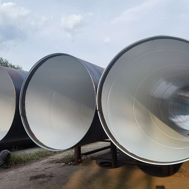 Large-diameter coated pipe on stands with the lined bore visible — coating resistance on both surfaces governs how much CP current the system will draw over its life.
Coating Resistance and Current Demand
The primary function of the external coating in a combined CP-coating system is to reduce CP current demand by maximizing the electrical resistance between the pipe surface and the surrounding soil. High coating resistance means low CP current demand, smaller rectifiers, wider anode spacing, and lower operating cost over the pipeline life.
Coating transition resistance is a key design parameter, typically measured in ohm·m² from a current interruption test or a close-interval potential survey. Representative values for well-applied pipeline coatings:
| Coating Type | Typical Coating Resistance (Ω·m²) |
|---|---|
| 3LPE (4.5 mm total thickness) | 10⁶ – 10⁸ |
| 3LPP (4.5 mm total thickness) | 10⁶ – 10⁸ |
| Single-layer FBE (400 µm) | 10⁴ – 10⁶ |
| Coal tar enamel | 10⁴ – 10⁵ |
| Bare steel | < 1 |
A 3LPE-coated pipeline requires orders of magnitude less CP current than an FBE-only or bare steel pipeline of the same diameter and length. This translates directly to rectifier station count, anode bed size, and power cost over the pipeline life — making coating quality a capital investment decision, not just a corrosion protection specification. The end-of-life resistance value — not the commissioning value — is the correct basis for CP design.
Cathodic Disbonding: The Critical Interaction
Cathodic disbonding is the loss of adhesion between the coating and the steel surface at a holiday edge, caused by the CP electrochemical reaction. When current flows from the soil through a coating holiday onto the pipe surface, the cathodic reaction generates hydroxyl ions (OH⁻) at the steel surface. At high local concentrations, these ions attack the coating-to-steel bond and progressively enlarge the disbonded zone around the original holiday.
All external coatings experience some cathodic disbonding, but the rate differs substantially by coating type:
- FBE — good cathodic disbonding resistance due to the crosslinked epoxy chemistry and strong polar bonding to the steel surface. FBE disbonds slowly and the disbonded area remains small under normal CP potentials.
- 3LPE / 3LPP — the polyethylene and polypropylene topcoats have deliberately low adhesion to the FBE undercoat (the interface is formulated to allow movement rather than cracking). If the FBE undercoat disbonds, the PE or PP layer peels with it and can create large shielded zones.
- Bitumen and coal tar — poor cathodic disbonding resistance; largely superseded by FBE-based systems for new construction.
Cathodic disbonding test requirements are specified in ASTM G8 (for pipe coating systems generally) and ASTM G42 (at elevated temperature). A well-performing coating system should show less than 15–20 mm radius of disbonding after 30 days at the CP protection potential.
Cathodic Shielding: The Hidden Risk
Cathodic shielding occurs when a disbonded coating prevents CP current from reaching the steel surface underneath the disbonded zone. Unlike a coating holiday, which is open to the soil electrolyte and accessible to CP current, a shielded disbond traps corrosive soil water under the coating with no current flow — effectively creating a corrosion cell that CP cannot reach.
Shielding risk is highest for:
- High-density coatings such as polyethylene topcoats, which form a near-watertight disbond
- Tape wraps on girth welds and field joints, which peel in a manner that seals the interface
- Any coating that disbonds as a large, cohesive sheet rather than in small localized zones
FBE is less susceptible to shielding than PE topcoat systems because FBE disbonds in a more localized manner that allows electrolyte access to the disbonded zone, preserving the CP current path. This is a key reason that FBE remains the preferred coating for sour service pipelines and directional-drilled crossings where aggressive soil conditions are expected to challenge coating adhesion.
Coating Selection for Combined CP Systems
| Coating System | CP Current Demand | Cathodic Disbonding Resistance | Shielding Risk | Best For |
|---|---|---|---|---|
| 3LPE (FBE + PE topcoat) | Very low | Moderate (FBE layer) | Moderate (PE topcoat) | Buried onshore, temperate climate |
| 3LPP (FBE + PP topcoat) | Very low | Moderate (FBE layer) | Moderate (PP topcoat) | Buried, operating temperature >60°C |
| Dual-layer FBE | Low | Low (excellent) | Very low | Sour service, directional drill crossings, wet environments |
| Single-layer FBE | Low–medium | Low (excellent) | Very low | Short-distance, high mechanical risk sections |
| Liquid epoxy (field joint) | Low–medium | Low | Very low | Girth welds, field joints |
| Heat shrink sleeve (field joint) | Low | Medium | Moderate | Standard girth welds, ambient temperature |
For sour service pipelines where the soil contains significant H2S or sulphate-reducing bacteria (SRB), the protective potential criterion tightens to −950 mV CSE per NACE SP0169, which increases CP current demand. In these cases, coating quality is critical to keeping that current demand within the rectifier and anode bed design limits. Note also that this tighter criterion further narrows the protection window for high-strength grades, as described in the insight callout above.
For a detailed comparison of 3LPE, FBE, and 3LPP coating systems including temperature range and mechanical performance, see the 3LPE, FBE, and 3LPP pipe coating selection guide →.
When NOT to Use SACP on Long Pipelines
Sacrificial anode CP is appropriate for specific situations but becomes the wrong tool when pipeline characteristics or environment fall outside its effective range. The decision table below identifies conditions where ICCP must replace SACP.
| Condition | Preferred Approach | Reason |
|---|---|---|
| Pipeline > 30 km onshore with grid power | ICCP | SACP anode consumption cost exceeds ICCP rectifier cost for long pipelines |
| Soil resistivity < 50 Ω·m | ICCP with controlled output | Low resistivity drives excess SACP current → overprotection risk on high-strength grades |
| X70 or X80 pipeline | ICCP with precise output control | SACP potential is harder to control; overprotection risk requires adjustable current source |
| High SRB activity with −950 mV CP requirement | ICCP | SACP magnesium anodes cannot sustain −950 mV in high-resistivity soils; ICCP provides headroom |
| Sections crossing stray current zones (rail or HVDC) | ICCP with stray current mitigation | SACP cannot counteract externally induced stray currents; ICCP with bonding and decoupling required |
The most common misapplication is specifying SACP for a long-distance onshore pipeline because the capital cost is lower: no rectifier stations, no power supply infrastructure. The error in this logic appears at year 10–15 when anode consumption accelerates with coating degradation and the anode beds must be replaced — a trench-open operation that costs more than the rectifier stations would have. For any buried gas or oil transmission pipeline above 30 km with accessible grid power, the ICCP life-cycle economics favour the rectifier-based system from the first design review.
Holiday Testing and CP Design Interaction
Holiday testing is performed after coating application and before burial to detect coating defects. The test voltage depends on the coating type and thickness:
- Single-layer FBE (400 µm): 5 V per micron per NACE SP0188 — approximately 2,000 V for a 400 µm coating
- 3LPE / 3LPP (4.5 mm total): high-voltage spark test at 25–30 kV, per the applicator specification
- Liquid epoxy field joint: spark test per manufacturer specification, typically 5–6 kV
- Heat shrink sleeve field joint: spark test at voltage determined by sleeve thickness, typically 15–20 kV
All detected holidays must be repaired and re-tested before burial. The residual holiday density after repair — typically measured in holidays per kilometre — is an input to the CP current density calculation. The lower the residual holiday rate, the lower the current demand at installation and the longer the anode or rectifier service life before a first upgrade is required.
A common design error is calculating CP current demand from an optimistic low holiday rate at installation and failing to include a coating degradation factor for the end of the design life. NACE SP0169 requires that the CP system be designed for the current demand at end of coating life, not at first commissioning — typically a factor of 3–10 increase in current density over a 30-year life for polyethylene-based coatings.
CP Current Demand: Commissioning vs End-of-Life Design
The following worked calculation shows how the same pipeline section produces radically different CP current demand at commissioning, mid-life, and end of life. The numbers demonstrate why sizing rectifiers for commissioning current leaves a pipeline unprotected within the first decade.
Pipeline parameters: 10-km section of 24-inch (609.6 mm OD) buried pipeline in moderate-resistivity soil (50–100 Ω·m). Coating system: 3LPE per ISO 21809-1. Bare steel current density in moderate soil: 15 mA/m².
Step 1 — Calculate total external pipe surface area:
Total area = π × OD (m) × length (m) = π × 0.6096 m × 10,000 m = 19,145 m²
Step 2 — At commissioning (3LPE coating, holiday rate 0.01% bare steel):
Bare steel area = 19,145 m² × 0.0001 = 1.91 m²
CP current demand = 1.91 m² × 15 mA/m² = 28.7 mA ≈ 30 mA
Step 3 — At 15 years (coating degraded, holiday rate 0.05%):
Bare steel area = 19,145 m² × 0.0005 = 9.6 m²
CP current demand = 9.6 m² × 15 mA/m² = 143 mA (5× commissioning demand)
Step 4 — At end of life, 30 years (holiday rate 0.10%):
Bare steel area = 19,145 m² × 0.001 = 19.1 m²
CP current demand = 19.1 m² × 15 mA/m² = 287 mA (10× commissioning demand)
Step 5 — Apply design margin for soil resistivity seasonal variation:
287 mA × 1.25 (25% margin) = 359 mA → design rectifier for ≈ 360 mA
The rectifier for this 10 km, 24-inch section must be rated for 360 mA minimum. A commissioning-only design that specified 30 mA would leave the pipeline without adequate protection from approximately year 5 onward as the coating holiday rate rises past 0.01%. Multiply this across a 100-km pipeline with ten such sections and the consequence of the original sizing error is ten undersized rectifiers, all requiring costly replacement before the pipeline reaches mid-life.
Design Workflow for a Combined System
A combined external coating and CP system is designed in the following sequence:
Step 1 — Define service conditions: soil resistivity (measured by Wenner four-pin method), soil pH, moisture content, SRB activity potential, operating temperature, pipeline diameter, wall thickness, and design life.
Step 2 — Select coating system: based on operating temperature, soil type, mechanical risk during backfill, and any trenchless installation requirements. For temperatures above 60°C, 3LPP or dual-layer FBE is required. For directional-drilled crossings, dual-layer FBE is preferred due to mechanical resistance during pull-through.
Step 3 — Specify coating performance requirements: minimum dry film thickness, adhesion pull-off strength (ASTM D4541, minimum 5 MPa), cathodic disbonding test (ASTM G8 or G42), holiday test voltage, and acceptance criteria for residual holiday density.
Step 4 — Calculate CP current demand: using initial and end-of-life coating resistance values. Follow the commissioning-vs-end-of-life methodology shown in the worked calculation above. Apply a 20–25% design margin for uncertainty in soil and coating ageing behaviour.
Step 5 — Select CP system type: ICCP for long pipelines with grid power; SACP for offshore or remote onshore. Refer to the "When NOT to Use SACP" table for conditions that require ICCP regardless of capital cost preference.
Step 6 — Design anode bed or anode bracelet layout: for ICCP, calculate rectifier output, anode bed resistance, and station spacing. For SACP, select bracelet anode type (zinc or aluminum for seawater; magnesium for high-resistivity soil) and calculate spacing based on current output per anode.
Step 7 — Specify field joint coating: field joints are the highest CP current demand zone in any buried pipeline. Specify the same electrical resistance requirement at field joints as at the parent pipe. Include holiday test voltage and acceptance criteria specific to the field joint coating system.
Step 8 — Plan CP monitoring: install test stations at regular intervals — typically every 1–2 km — for periodic pipe-to-soil potential surveys. For ICCP, install remote monitoring on rectifiers. Schedule annual close-interval potential surveys (CIPS) per NACE SP0169.
For field joint coating system options and selection criteria, see the field joint coating systems guide →.
Combined System Failure Modes to Specify Against
Three failure modes account for the majority of combined CP-coating system failures seen on long-distance buried pipelines. Each is preventable at the specification and PO stage. Each is expensive to remediate after commissioning.
Failure Mode 1 — Rectifier undersizing for end-of-life coating degradation
Mechanism: CP system designed for commissioning holiday rate (0.01% bare steel); rectifier output sized for 30–50 mA. After 10–15 years, coating holiday rate rises to 0.05–0.1%; current demand increases 5–10×; rectifier reaches maximum output; pipe-to-soil potential rises to −700 to −750 mV CSE — insufficient protection. Corrosion initiates at coating holidays faster than the pipeline integrity management programme detects.
Diagnostic: Annual close-interval potential survey (CIPS) shows protection potential gradually rising toward −800 mV CSE across multiple test stations; readings do not improve with rectifier output increase (already at maximum). Rectifier ammeter shows output at rated maximum continuously.
Fix: Size CP rectifier for end-of-life current demand (×10 commissioning current for polyethylene coatings over 30 years, as shown in the worked calculation above). Specify rectifier with minimum 50% spare capacity above end-of-life design current. Include rectifier sizing basis in CP design document — attach to pipe coating PO so the coating specification and CP design are linked.
Failure Mode 2 — Stray current interference from adjacent infrastructure
Mechanism: Buried pipeline runs parallel to or crosses near a DC-electrified railway or an HVDC power line. DC stray current from the railway return rail or the HVDC earth electrode enters the pipeline at low-resistivity zones and exits at other locations. Current discharge points corrode at the rate determined by Faraday's law: 1 ampere of discharge corrodes approximately 9 kg of steel per year. Pipeline potential at discharge points fluctuates outside the −850 to −1,100 mV protection window regardless of rectifier output.
Diagnostic: Pipe-to-soil potential varies cyclically with train schedule or shows correlated variations with HVDC operation time. ILI run identifies pitting at consistent geographic locations correlated with infrastructure crossing points.
Fix: Conduct stray current interference survey during pipeline design phase — before route is finalised. Install AC/DC mitigation at crossing points: polarisation cells, decoupling devices, or gradient control mats. Include stray current interference as a route selection criterion in the design basis.
Failure Mode 3 — Cathodic shielding at disbonded PE topcoat
Mechanism: 3LPE outer polyethylene layer disbonds as a large cohesive sheet — commonly at directional drill pull-through zones, sharp rock impact points, or thermal cycling locations. The disbonded PE sheet seals the interface completely, trapping corrosive soil water between the PE and the steel. CP current cannot penetrate the intact PE shield. Pipe-to-soil potential at the nearest test station reads within the protection window, because the test station measures the open-soil potential, not the potential under the shield. The steel under the shield corrodes at full unprotected soil corrosivity rate.
Diagnostic: DCVG (direct current voltage gradient) survey detects anomalies — points where potential gradient is lower than expected for the registered holiday size, indicating the current drain is from a shielded disbond rather than an open holiday. Excavation at DCVG anomalies reveals an intact PE sheet overlying active corrosion.
Fix: Specify dual-layer FBE (no PE topcoat) for all directional drill sections, river crossings, and rocky terrain sections expected to generate impact or pull-through loads. Dual FBE disbonds in small, localized zones that allow electrolyte access and preserve the CP current path. Conduct DCVG survey within 2 years of commissioning for the first integrity cycle.
Purchase Order Guidance
Minimum PO line items for coated line pipe with CP system:
- Coating type (3LPE, 3LPP, or dual-layer FBE) with minimum total dry film thickness in mm
- Cathodic disbonding test requirement (ASTM G8 at −1,500 mV at specified temperature and duration)
- Holiday test voltage and maximum allowable residual holiday frequency (per NACE SP0188)
- FBE adhesion test (ASTM D4541, minimum pull-off strength after cathodic disbonding exposure)
- Field joint coating type and require field joint kit supply included in the pipe consignment
- EN 10204 3.1 MTC for base pipe and a separate coating inspection certificate
- Specify CP anode type if SACP bracelets are to be factory-fitted
Formal procurement trap — wrong PO, what ships, correct language:
Wrong PO: "API 5L X65M PSL2, 24-inch × 14.3 mm, 3LPE coating per ISO 21809-1, EN 10204 3.1 MTC."
What ships: Mill applies 3LPE to ISO 21809-1 defaults. No cathodic disbondment test criterion stated. No end-of-life coating resistance value specified for CP design. No field joint coating system included in scope. CP designer has no coating resistance data to use — assumes best-case for sizing, producing the rectifier undersizing failure mode described above.
Correct PO additions: "3LPE minimum 3.5 mm total thickness; cathodic disbondment per ISO 21809-1 maximum 8 mm radius at 65°C; initial coating transition resistance minimum 10⁶ Ω·m²; end-of-life coating resistance design value for CP sizing = 10⁴ Ω·m² at 30 years; field joint kit (3-layer HSS, DIN 30672 Class C, temperature rated to match mainline coating) included in PO scope; EN 10204 3.2 MTC with separate coating inspection certificate."
The combined-system procurement trap: The most common combined-system error is specifying the parent pipe coating correctly but omitting the field joint coating from the PO scope, assuming the main contractor will source it separately. In practice, field joint coatings sourced separately often do not match the parent pipe coating's resistance specification, and the higher CP current demand at field joints drains the rectifier output or accelerates anode consumption. Specify the full field joint kit — primer, heating equipment specification if applicable, and sleeve or liquid epoxy system — on the same PO as the parent pipe coating to ensure system compatibility and avoid a CP overload scenario during commissioning.
What to verify before backfilling: Confirm all holidays have been repaired and re-tested. Confirm field joint coating has been applied and spark-tested per specification. Verify that the reference electrode for pre-backfill potential measurements has been checked against a known standard. Record the initial pipe-to-soil potential at each test station position before backfilling — this is the commissioning baseline for the full CP monitoring programme.
Frequently Asked Questions
Why does a coated pipeline still need cathodic protection?
No pipeline coating is perfect at installation, and all coatings degrade over time. Coating defects — called holidays — expose bare steel to soil or seawater. Cathodic protection (CP) provides the electrochemical driving force that prevents corrosion at coating holidays and at locations where the coating disbonds from the pipe surface. The two systems are complementary: coatings reduce the bare steel area that CP must protect, and CP suppresses corrosion at the residual defects that coatings cannot prevent.
What is the difference between impressed current and sacrificial anode cathodic protection?
Impressed current cathodic protection (ICCP) uses an external power source to drive direct current through the soil and onto the pipeline, making the pipe surface cathodic. Sacrificial anode cathodic protection (SACP) uses more electronegative metals — zinc, aluminum, or magnesium — that corrode preferentially and supply current without an external power source. ICCP is used for long onshore pipelines where grid power is available; SACP is standard for offshore pipelines and shorter buried sections where external power is impractical.
What is cathodic disbonding and how does it affect coating selection?
Cathodic disbonding occurs when the electrochemical reaction at a coating holiday generates hydroxyl ions that migrate under the coating edge and reduce adhesion. High-resistance coatings such as 3LPE limit the total CP current demand but can shield the steel from CP current once the coating has disbonded, trapping corrosion beneath. FBE has superior cathodic disbonding resistance compared to polyethylene topcoats because its crosslinked epoxy chemistry bonds more durably to the steel surface.
What protection potential range is required for buried pipeline cathodic protection?
NACE SP0169 specifies a pipe-to-soil potential of −850 mV or more negative versus a copper/copper sulfate reference electrode (CSE) as the criterion for adequate cathodic protection of buried steel pipelines. For high-temperature pipelines where sulphate-reducing bacteria are active, a potential of −950 mV CSE may be required. Overprotection — potentials more negative than −1,100 mV CSE — should be avoided for high-strength pipe to prevent hydrogen embrittlement.
How does coating quality affect the required CP current density?
A well-applied 3LPE or FBE coating reduces the exposed bare steel area to less than 0.1% of the total pipe surface at initial installation, dramatically reducing the CP current required to achieve protection potential. As the coating ages and the holiday rate increases, the current demand grows. NACE SP0169 requires that CP systems be designed with sufficient current capacity to maintain protection at end of coating life, not just at commissioning.
What holiday testing is required for pipeline coating before CP is applied?
Holiday (spark) testing is required on all external pipeline coatings before burial to identify coating defects. FBE coatings are tested at 5 V per micron of coating thickness per NACE SP0188. 3LPE and 3LPP coatings are tested using high-voltage spark detectors at voltages specified by the applicator. All holidays must be repaired before backfilling. Residual holiday density after repair is an input to the CP design current density calculation.
What is cathodic shielding and which coatings are most at risk?
Cathodic shielding occurs when a disbonded coating prevents CP current from reaching the steel surface underneath the disbonded zone. The disbonded area cannot receive CP protection and corrodes, often more aggressively than if no coating were present, because the shield also traps corrosive species. High-density polyethylene topcoats and tightly-bonded tape wraps are most susceptible to shielding. FBE coatings are less susceptible because they tend to disbond in a manner that allows electrolyte access to the disbonded zone.
How are field joints addressed in a combined CP and coating system?
Field joints — the uncoated sections at each pipe girth weld — are the highest-risk locations in any CP-coating system. Each field joint coating must achieve the same electrical resistance and adhesion performance as the factory coating to avoid creating high current demand spots that destabilize the overall CP system. Heat shrink sleeves and liquid epoxy field joint coatings are the most common choices; the CP design should calculate field joint current density separately from parent pipe, accounting for the typically higher holiday rate on site-applied coatings.