
Finned tubes are the core heat transfer element in air-cooled heat exchangers, fired heaters, and shell-and-tube exchangers where one fluid has a significantly lower heat transfer coefficient than the other. Adding external fins to a smooth tube increases the outer surface area by a factor of 2 to 10, allowing equipment designers to reduce the number of tube passes, the bundle width, or the overall footprint without sacrificing thermal duty. Selecting the right fin type — extruded, high-frequency welded, or mechanically bonded — and the right base tube material determines equipment life and long-term thermal performance.
ZC Steel Pipe manufactures finned tubes with carbon steel and alloy steel base tubes to ASTM A179, ASTM A192, and ASTM A213 T11/T22/T91, serving EPC projects in Africa, the Middle East, South America, and Southeast Asia with EN 10204 3.1 mill certificates.
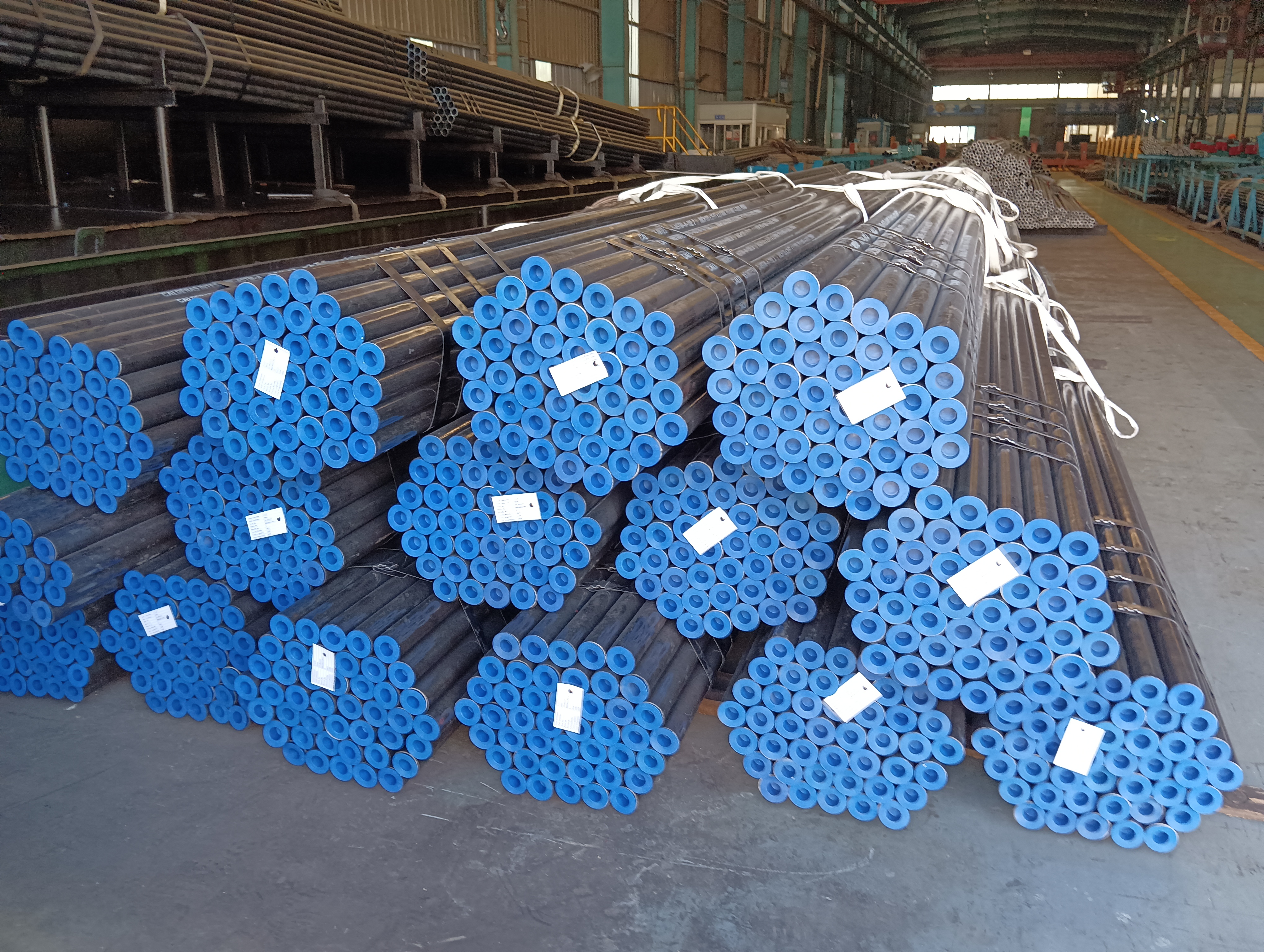 Seamless heat-exchanger tube bundles with protective end caps and ID tags, from a ZC ASTM A192 supply to South America.
What we see on orders: On an East Africa refinery project, the equipment datasheet specified "helical finned tubes, 6 FPI, aluminum fins, API 661." The equipment vendor supplied tension-wound L-foot crimped aluminum fins — technically helical, technically aluminum, technically 6 FPI, technically API 661-compliant on dimensions. The process air cooler operated at 85°C tube-wall temperature. Within 18 months, thermal performance had degraded by 22% from the clean-condition rating. The root cause was thermal relaxation of the L-foot bond at 85°C — a mechanism that passes every dimensional and visual check. The bundle was replaced with HFRW welded carbon steel fins at 2.5× the original bundle cost plus a 4-week outage. Specifying "HFRW welded carbon steel fins" or "extruded bimetallic aluminum fins, bond per API 661 peel test requirements" closes this ambiguity entirely.
What Are Finned Tubes?
A finned tube is a plain tube with fins attached to or integrally formed from its outer surface. The fins extend the effective heat transfer area beyond what the bare tube OD alone provides. This is particularly valuable on the air side or shell side of a heat exchanger, where the heat transfer coefficient is low compared with the tube-side fluid. For a gas (air or combustion products) flowing over a tube bank, the air-side heat transfer coefficient is typically 20–80 W/m²·K, compared with 500–5000 W/m²·K on the tube side for liquid or steam. Adding fins reduces the dominant thermal resistance on the air side and brings the overall heat transfer coefficient closer to the tube-side value.
The key performance parameter of a finned tube is its external surface area per unit of tube length, expressed in m²/m or ft²/ft. A 25.4 mm OD bare tube has an external surface area of approximately 0.080 m²/m. A finned tube of the same bare OD with fins can reach 0.4–0.8 m²/m depending on fin height, pitch, and thickness — a 5 to 10 times increase.
External Surface Area: Finned vs Bare Tube
The surface area ratio can be calculated directly. For a 25.4 mm OD bare tube vs a finned tube at 6 FPI with 12.7 mm fin height:
Step 1 — Bare tube external area per metre: A_bare = π × D × L = π × 0.0254 × 1.0 = 0.0798 m²/m
Step 2 — Finned tube calculation (6 FPI, 12.7 mm fin height, 0.41 mm aluminum fin thickness): Fin pitch = 25.4 / 6 = 4.23 mm per fin Number of fins per metre: 1000 / 4.23 = 236 fins/m Finned OD = 25.4 + 2 × 12.7 = 50.8 mm = 0.0508 m Area per fin (annular face, both sides): 2 × π/4 × (0.0508² − 0.0254²) = 2 × π/4 × (0.002581 − 0.000645) = 2 × π/4 × 0.001936 = 0.003041 m² per fin Total fin area per metre: 236 × 0.003041 = 0.717 m²/m Bare tube area between fins per metre: π × 0.0254 × (1.0 − 236 × 0.00041) = 0.0798 × (1.0 − 0.0967) = 0.0798 × 0.903 = 0.0721 m²/m Total finned tube external area: 0.717 + 0.0721 = 0.789 m²/m
Step 3 — Surface area ratio: 0.789 / 0.0798 = 9.9× the bare tube area
A finned tube at 6 FPI with 12.7 mm fins provides approximately 10× more external surface area than the bare tube of the same OD. This allows a bundle to deliver the same heat duty in roughly one-tenth the number of tube passes, or approximately one-tenth the total tube length — which is the engineering justification for finned tubes in air-side-limited heat transfer applications.
Fin Tube Types by Geometry
Helical (Spiral) Fin Tubes
The most common geometry for air-cooled heat exchangers. A continuous fin strip is wound helically along the tube length, producing a spiral array of fins perpendicular to the tube axis. The fin strip can be wound tension-free (embedded or grooved), under tension (wrap-on), or continuously welded. Helical fins produce relatively uniform air-side velocity distribution and are suitable for most ACHE bundle designs.
Longitudinal (L-type or Stacked) Fin Tubes
Fins run parallel to the tube axis rather than perpendicular to it. Longitudinal fins are used in annulus heat exchangers where two coaxial tubes carry different fluids, and in natural convection applications where air rises vertically along the tube. They are less common than helical fins in forced-draft heat exchangers.
Low-Fin Tubes (Integral Fins)
Low-fin tubes for shell-and-tube applications are produced by machining or rolling helical fins directly from the tube wall, with fin heights of 1–1.6 mm and fin pitches of 19 fins/inch (748 FPM) or higher. Because the fins are machined from the parent tube material, there is no fin-to-tube contact resistance. Low-fin tubes per TEMA are used to enhance shell-side performance without significantly reducing tube inside diameter.
Plate-Fin Tubes
A flat plate with punched holes is slid over multiple tubes in a bundle to form the air-side surface. Plate-fin geometry is dominant in automotive radiators and air conditioning coils but is less common in heavy industrial heat exchangers. ZC Steel Pipe supplies helical and longitudinal fin tube configurations rather than plate-fin bundles.
Manufacturing Methods
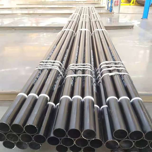 Strapped bundle of seamless base tubes on the shop floor, ready for finning.
Extruded Fin Tubes (Bimetallic)
An aluminum billet is hot-extruded over a pre-descaled inner tube using a die that forms the helical fins simultaneously. The aluminum is cold-worked against the steel tube surface under high pressure, creating mechanical interference contact. The process produces integral fins with very low contact resistance at the fin root, because the aluminum flows into micro-surface irregularities on the steel. Extruded fin tubes are manufactured to OD tolerances typically ±0.25 mm and are specified in API 661 as a standard fin tube type for temperatures up to approximately 200°C (400°F) with aluminum fins. Beyond this temperature, the differential thermal expansion between aluminum and steel begins to open the fin-root bond, increasing contact resistance.
High-Frequency Resistance Welded (HFRW) Fin Tubes
A pre-formed fin strip (typically carbon steel, stainless steel, or Inconel) is fed through a guiding die and spirally wound onto the rotating tube. A high-frequency resistance current passes through the fin-to-tube contact zone immediately before the pressure roll, locally melting both the fin foot and the tube surface and forging them together into a metallurgical bond. HFRW welding produces a continuous fusion weld at the fin root, resulting in zero contact resistance and the ability to operate at temperatures up to 400–450°C for carbon steel fins or up to 600°C for stainless steel fins. HFRW tubes are the preferred choice for refinery and petrochemical air coolers operating at elevated tube-wall temperatures.
Embedded (G-type) Fin Tubes
A groove is machined helically into the outer tube surface, then a fin strip is inserted into the groove and the groove edges are peened over to lock the fin base in place. The mechanical lock produces low contact resistance and good thermal conductivity across the fin-to-tube joint. G-type fins are limited to base tube materials with sufficient hardness to allow peening without cracking, and to service temperatures below approximately 260°C where differential expansion does not open the groove. G-type tubes are often used in economiser and preheater service.
Tension-Wound (L-foot) Fin Tubes
A fin strip with an L-shaped cross-section foot is tension-wound around the tube at high tension, with the foot lying flat against the tube surface. The contact pressure is maintained by the residual tension in the fin strip. Tension-wound fins offer the simplest and lowest-cost manufacturing process but also the highest thermal contact resistance of any fin type, because contact depends on mechanical pressure alone. Maximum service temperature for tension-wound aluminum fins is typically 120–150°C; beyond this, thermal relaxation of the fin foot tension occurs.
Base Tube and Fin Materials
| Base Tube Standard | Material | Max Service °C | Typical Application |
|---|---|---|---|
| ASTM A179 | Seamless low-carbon steel | 350 | General heat exchangers, condensers |
| ASTM A192 | Seamless carbon steel | 375 | Boiler economisers, moderate-pressure HX |
| ASTM A213 T11 | 1.25Cr–0.5Mo alloy steel | 510 | High-temperature refinery air coolers |
| ASTM A213 T22 | 2.25Cr–1Mo alloy steel | 550 | High-temperature refinery and gas plant |
| ASTM A213 T91 | 9Cr–1Mo–V alloy steel | 600 | Ultra-high-temperature creep service |
| ASTM A213 TP316L | Austenitic stainless | 870 | Corrosive process or shell-side fluids |
Fin materials and their thermal conductivity:
| Fin Material | Conductivity (W/m·K) | Max Temp (°C) | Notes |
|---|---|---|---|
| Aluminum 1060/1100 | 205 | 200 | Standard for ACHEs; light weight |
| Carbon steel | 50 | 450 | For high-temp; HFRW bond required |
| Stainless steel 316 | 16 | 600 | Offshore/chemical; HFRW bond |
| Copper | 385 | 200 | HVAC and low-temperature process |
The tables above highlight the key tension in finned tube selection: aluminum delivers 4× the thermal conductivity of carbon steel at the fin surface, but its 200°C bond limit constrains its use. In Middle East air cooler service with ambient temperatures above 45°C and high process-fluid temperatures, the tube-wall temperature during upset conditions can cross 200°C before the process engineer expects it. The carbon steel fin row in this table — HFRW-bonded — is the conservative choice for any service where tube-wall upset temperature cannot be guaranteed below 180°C.
For full mechanical property tables and heat treatment data for ASTM A192, A213 T11, T22, and T91 base tube grades, see the ASME Boiler Tube Spec Tables →
To convert between imperial and metric fin dimensions or temperature units, use the Unit Converter →
The fin bond type and the base tube material are independent selection criteria that must be addressed separately on every purchase order. A T22 alloy steel base tube (rated to 550°C) paired with extruded bimetallic aluminum fins is limited to 200°C by the fin bond — the tube is over-specified and the fin is the bottleneck. Conversely, a carbon steel base tube with HFRW carbon steel fins is limited to approximately 400°C by the base tube material, not the bond. Specifying only the base tube grade leaves the supplier free to select the most economical fin bond type, which may not match the process temperature requirement. Both the base tube grade and the fin bond type must be stated explicitly on the PO.
Standard Dimensions and Specifications
API Standard 661 (latest edition) defines the dimensional requirements and test requirements for fin tubes used in air-cooled heat exchangers for refinery and petrochemical service. Key API 661 dimensional parameters:
| Parameter | Typical Range |
|---|---|
| Bare tube OD | 19.05 mm (¾") to 50.8 mm (2") |
| Fin height | 9.525 mm (⅜") to 15.875 mm (⅝") |
| Fin pitch | 3–12 fins/inch (118–472 fins/m) |
| Fin thickness (aluminum) | 0.41 mm (0.016") minimum |
| Fin thickness (steel) | 0.89 mm (0.035") minimum |
| Finned length | Per equipment datasheet |
All dimensional values are subject to API 661 tolerances and the project specification. Verify actual dimensions against the current edition of API 661 before placing a purchase order. The minimum fin thickness values above (0.41 mm for aluminum, 0.89 mm for steel) are API 661 hard floors — suppliers quoting thinner fins are not compliant, and a PO that does not state minimum fin thickness leaves the supplier free to propose the lightest gauge that clears the tolerance band.
Tube length tolerances and ovality for base tubes comply with ASTM A179, ASTM A192, or ASTM A213 as applicable. Hydrostatic testing of base tubes is performed per the applicable ASTM standard before finning.
Applications in Heat Exchangers
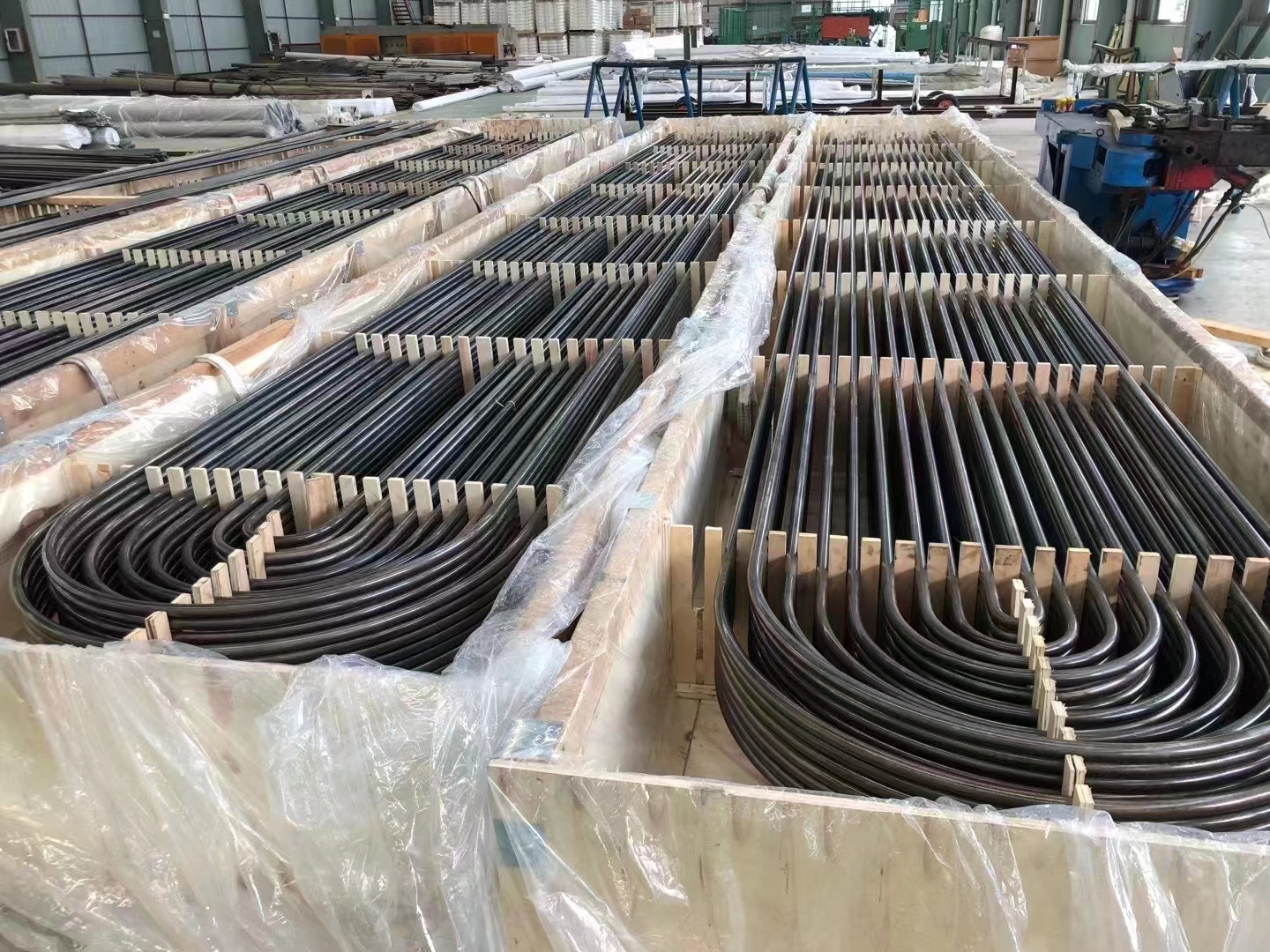 Crated U-tube bundles alongside a tube-bending machine in the workshop.
Air-Cooled Heat Exchangers (ACHEs)
ACHEs use forced-draft or induced-draft fans to move air across finned tube bundles. They are the dominant application for helical fin tubes in oil and gas, refinery, petrochemical, and power generation facilities. Typical ACHE fin tube service conditions are:
- Air inlet temperature: 25–50°C
- Process fluid outlet temperature: 60–300°C depending on fluid
- Tube-wall temperature: controlled by the internal process fluid
- Air-side fouling: dust, sand, salt in coastal and desert environments
ZC Steel Pipe supplies ACHE fin tubes with carbon steel and alloy steel base tubes for EPC projects in the Middle East, Africa, and South Asia where high ambient temperatures and dusty air require wide-pitch fins and robust fin bonding.
Shell-and-Tube Heat Exchangers (Low-Fin Tubes)
Low-fin tubes with 19 fins/inch (748 FPM) are used in TEMA shell-and-tube heat exchangers to boost shell-side area when the shell-side heat transfer coefficient is the limiting resistance. Common in reboilers, condensers, and coolers in refinery and petrochemical service. TEMA designates low-fin tube geometry and dimensional tolerances in its Standards (latest edition).
Fired Heater Economisers and Air Preheaters
Finned tubes are used in the convection section of fired heaters (process heaters) and boiler air preheaters to recover sensible heat from flue gas before it exits the stack. The high-fouling potential of flue gas containing soot and fly ash requires wide fin pitch (3–5 FPI) and robust fin bonding. Alloy steel base tubes to ASTM A213 T11 or T22 are standard for flue gas temperatures above 400°C.
Steam Generator Economisers
In utility and industrial boilers, economiser tubes preheat boiler feedwater using exhaust gas from the furnace. Finned tubes reduce the length of economiser required for a given preheat duty. ASTM A192 carbon steel is the standard base tube for economisers operating below 375°C.
When NOT to Use Extruded Bimetallic Fin Tubes
Extruded bimetallic aluminum fin tubes are the lowest-cost and most widely available fin tube type. They are the correct choice for clean utility and low-temperature process service. There are five conditions where they are the wrong choice, and procuring them for any of these conditions will produce a performance deficit within one to three years.
| Condition | Correct fin type | Why extruded fails |
|---|---|---|
| Tube-wall temperature > 200°C | HFRW welded steel or alloy fins | Differential expansion (Al coeff 23 × 10⁻⁶/°C vs steel 12 × 10⁻⁶/°C) opens fin-root bond, increasing contact resistance permanently |
| Steam-out cleaning at 150°C or above | HFRW welded | Steam temperature exceeds extruded aluminum thermal limit; bond degrades with each cleaning cycle |
| Offshore or coastal installation (salt air) | HFRW with epoxy coating or SS fins | Galvanic cell (aluminum anode / carbon steel cathode) forms at fin root in marine atmosphere; aluminum corrodes selectively |
| API 661 refinery or petrochemical process air cooler | HFRW carbon steel fins | API 661 standard preference for process service; extruded aluminum limited to utility and low-temp process streams |
| Repeated thermal cycling (>2 × /year startup/shutdown) | HFRW welded | Repeated differential expansion fatigue weakens the cold-work interference bond progressively |
Three of the five conditions in this table are frequently mis-assessed because the equipment datasheet records normal operating temperature, not upset or cleaning temperature. A gas cooler with a normal tube-wall temperature of 120°C may steam-clean at 160°C during maintenance turnarounds — which puts it squarely in the third row of this table even though normal service appears compliant.
Fin Tube Failure Modes to Specify Against
The failure modes below are the three that appear most often in fin tube replacement orders we process. Each one was preventable at the PO stage. The mechanism column explains why the failure occurs; the diagnostic column explains how to detect it before full bundle replacement becomes necessary.
Failure Mode 1 — Fin-root bond degradation from tube-wall temperature exceedance
Mechanism: Extruded bimetallic aluminum fin tube installed in a gas cooler where the design tube-wall temperature is stated as 95°C, but the actual peak tube-wall temperature during maximum-load operation reaches 215°C. At peak conditions, the aluminum sleeve expands relative to the steel tube, creating a micro-gap at the fin root. Over 2–3 years of seasonal cycling between ambient and 215°C, the gap becomes a permanent delamination zone, increasing contact resistance from less than 0.0002 m²·K/W to more than 0.0008 m²·K/W.
Diagnostic: Progressive increase in process outlet temperature at constant flow conditions — the air cooler is "losing capacity" without any visible mechanical failure. Infrared thermography of the bundle shows warm streaks along tubes with degraded fin bonds, while adjacent tubes with intact bonds are cooler. Air-side pressure drop is unchanged (fins are still physically present), which misleads operators into suspecting a process-side cause rather than a fin bond failure.
Fix: Specify the maximum tube-wall temperature on the fin tube purchase order — include upset conditions and steam-out temperature, not just normal design temperature. For any service above 150°C, specify HFRW welded fin tubes. After re-tubing with HFRW, the performance excursion does not recur.
Failure Mode 2 — Galvanic corrosion at aluminum fin / carbon steel tube interface in coastal service
Mechanism: Extruded bimetallic aluminum fin tubes on an offshore topside or coastal refinery platform. Salt spray condenses on the fin surfaces and penetrates to the fin-root contact zone between the aluminum sleeve and the carbon steel tube. In the electrolytic environment (salt solution), carbon steel acts as the cathode (noble metal) and aluminum acts as the anode (active metal), creating a galvanic cell that selectively corrodes the aluminum at the fin root. After 3–5 years, the aluminum at the fin root is consumed, destroying thermal contact even though the fin visually appears intact.
Diagnostic: White-powder corrosion product (aluminum oxide hydrate) visible at the fin base under magnification or hand lens inspection. Infrared thermographic scan of the bundle shows elevated tube temperatures along the gas flow direction, consistent with loss of external surface efficiency. API 661 fin bond pull-off test on removed sample tubes confirms bond strength below the minimum.
Fix: For offshore or within 5 km of coastline, specify HFRW welded carbon steel fins (not aluminum) or extruded aluminum fins with epoxy coating applied to the entire fin root zone. Implement 6-monthly visual inspection intervals. Do not use bare extruded aluminum fin tubes in marine atmospheres without a fin root barrier coating.
Failure Mode 3 — Tension-wound crimped fin accepted through drawing approval without bond verification
Mechanism: The project specification states "finned tubes per API 661, 6 FPI" without specifying the bond type. The equipment vendor submits a dimensional drawing that shows the correct fin pitch, height, and thickness. The review engineer approves the drawing without noticing that the fin root geometry shown is an L-foot crimped design rather than the HFRW weld profile. The equipment is manufactured with crimped fins, which pass all dimensional checks. At 140°C operating tube-wall temperature, the L-foot relaxes within 8–12 months, producing a 20–25% heat duty deficit.
Diagnostic: Performance monitoring data shows progressive increase in process outlet temperature against a flat trend line in process flow and inlet conditions. The only way to confirm fin bond type without physical access is to request the manufacturing process record — a current-continuity weld log (HFRW) or a press force record (extruded) will not exist for crimped fins.
Fix: Require the fin bond type to be explicitly stated on the vendor's dimensional drawing, confirmed against the project specification. Make "HFRW welded fin root, confirmed by current-continuity weld monitoring record" or "extruded bimetallic bond, confirmed by peel strength test per API 661" a mandatory hold point in the MTC, not just a drawing review item. Reject any fin tube MTC that does not include bond verification data.
Purchase Order Guidance
A purchase order for finned tubes should include:
- Base tube standard and grade: ASTM A179, A192, A213 Grade (T11, T22, T91, TP316L)
- Base tube OD and minimum wall thickness: in millimetres or inches
- Fin type: extruded (bimetallic), HFRW welded, G-type embedded, or tension-wound
- Fin material and alloy: e.g., aluminum alloy 1100, carbon steel, SS 316
- Fin height and pitch: in mm and fins/inch
- Fin thickness: minimum value in mm
- Finned length and bare end length: per equipment datasheet
- Applicable standard: API 661 (for ACHEs) or project specification
- Test requirements: base tube hydrostatic test, fin bond peel test, dimensional inspection
- MTC requirement: EN 10204 3.1 or 3.2
Procurement trap — confusing fin bond type with performance class:
Wrong PO: "Helical fin tube, 6 FPI, aluminum fins, 25.4 mm OD base tube, API 661 latest edition."
What ships: Supplier selects tension-wound L-foot crimped aluminum fins — the cheapest manufacturing method, fully compliant with API 661 dimensional requirements (fin pitch, fin height, fin thickness all verified by measurement). The word "helical" describes the fin geometry, not the bond type, so a crimped L-foot is technically helical.
Correct PO: "HFRW high-frequency resistance welded fin tube [or extruded bimetallic aluminum fin tube]; fin material aluminum alloy 1100 [or carbon steel]; fin height 12.7 mm; fin pitch 6 FPI; fin thickness 0.41 mm min (aluminum) [or 0.89 mm min (carbon steel)]; bond per API 661 — peel strength test records for extruded bimetallic, or current-continuity weld verification for HFRW, to be included on MTC; max tube-wall design temperature [state value in °C] confirmed against fin type limitation."
Procurement trap — omitting fin-to-tube bond testing: API 661 requires a minimum peel strength test for bimetallic extruded fins. Buyers who rely only on dimensional inspection will miss fin bond degradation introduced during incorrect finning process control. Require peel test results on the MTC for extruded and G-type tubes.
Frequently Asked Questions
What is a finned tube?
A finned tube is a heat transfer tube with fins attached to or formed from its outer surface to increase the effective heat transfer area. By replacing a smooth bare tube with a finned tube, engineers can achieve 2–10 times more external surface area within the same bundle footprint, which reduces equipment size and capital cost for a given heat duty.
What is the difference between extruded and welded fin tubes?
Extruded fin tubes are bimetallic: an outer aluminum sleeve is co-extruded over a steel or alloy steel inner tube, forming fins with zero contact resistance between the fin root and the tube. Welded (HF-welded) fin tubes are made by spirally winding a steel fin strip and continuously resistance-welding it to the tube OD. Welded fins have a metallurgical bond and can be used at higher temperatures than extruded aluminum fins, making them the preferred choice for refinery, petrochemical, and gas processing applications above 200°C.
What base tube materials are used for finned tubes?
Common base tube materials for finned tubes are carbon steel to ASTM A179 or A192 for moderate-temperature service, chrome-moly alloy steel to ASTM A213 Grade T11 or T22 for temperatures up to 550°C, T91 for high-creep service above 550°C, austenitic stainless steel (316L) for corrosive process fluids, and copper-nickel alloys for seawater or marine service. The base tube material is selected for the process-side fluid and operating temperature, while the fin material is selected for the air-side or shell-side environment.
What is fin pitch, and what range is typical?
Fin pitch is the number of fins per unit of tube length, expressed in fins per inch (FPI) or fins per metre (FPM). Typical ranges are 3 to 12 FPI (118 to 472 FPM) for air-cooled heat exchangers. Low fin pitches (3–5 FPI) are used where the air-side is fouling-prone (dusty, sandy environments). High fin pitches (8–12 FPI) are used where the air is clean and maximum heat transfer surface per tube is needed. For shell-and-tube heat exchangers, low-fin tubes with 19 fins/inch (748 FPM) are common to boost shell-side area with minimal impact on tube-side hydraulics.
What standards govern finned tube heat exchangers?
API Standard 661 (Air-Cooled Heat Exchangers for General Refinery Service) is the primary procurement standard for fin tubes used in air-cooled heat exchangers. TEMA (Tubular Exchanger Manufacturers Association) governs shell-and-tube heat exchangers including low-fin tubes. ASME Section VIII Division 1 governs the pressure design of heat exchanger shells and headers. HEI (Heat Exchange Institute) publishes standards for surface condensers and feedwater heaters. Individual fin tube manufacturing specifications are typically defined in the purchaser's project specification or the relevant API 661 equipment datasheet.
How do finned tubes fail in service?
The most common failure modes for finned tubes are fin bond degradation (for mechanically bonded types), galvanic corrosion between the fin and base tube materials (especially aluminum fins on carbon steel tubes in coastal or humid environments), erosion of fin tips by high-velocity air carrying particulates, and creep relaxation of the fin root contact pressure at elevated temperatures. For welded fins, failure modes include weld cracking at the fin-to-tube joint from thermal cycling and hydrogen embrittlement in sour gas service. Regular visual inspection, pressure drop monitoring, and infrared thermography help detect bond degradation before it causes a significant loss of thermal performance.
What fin materials are used and how do they compare?
Aluminum fins are the dominant choice for air-cooled heat exchangers due to their high thermal conductivity (205 W/m·K), low cost, and light weight. Carbon steel fins are used where higher temperatures or stronger mechanical bonds are required, at the cost of lower conductivity (50 W/m·K). Stainless steel fins are specified for corrosive air-side environments such as offshore platforms or chemical plants where chloride stress corrosion cracking of aluminum or carbon steel is a risk. Copper fins offer very high conductivity (385 W/m·K) and are used in HVAC and low-temperature process applications.
Does ZC Steel Pipe supply finned tubes?
Yes. ZC Steel Pipe supplies finned tubes for air-cooled heat exchangers and shell-and-tube heat exchangers. Our range covers carbon steel base tubes to ASTM A179 and A192, alloy steel base tubes to ASTM A213 T11, T22, and T91, and high-frequency welded fin tubes with aluminum or carbon steel fins. We serve EPC projects in Africa, the Middle East, South America, and Southeast Asia, and supply mill test certificates to EN 10204 3.1.