
Fin pitch — the spacing between adjacent fins on a heat transfer tube — is the single most important geometric variable in an air-cooled or fin-tube heat exchanger design. It determines how much surface area is packed into a given bundle volume, how much resistance the air side sees in terms of pressure drop, and how susceptible the bundle is to fouling. Engineers who understand the relationship between fin pitch, heat transfer performance, pressure drop, and surface efficiency can make informed trade-offs between equipment size, fan power, and fouling tolerance — and can avoid the costly error of specifying the wrong pitch for a demanding site environment.
ZC Steel Pipe manufactures finned tubes across a range of fin pitches for air-cooled heat exchangers and heat recovery applications, supplying EPC projects in the Middle East, Africa, South America, and Southeast Asia with mill test certificates to EN 10204 3.1.
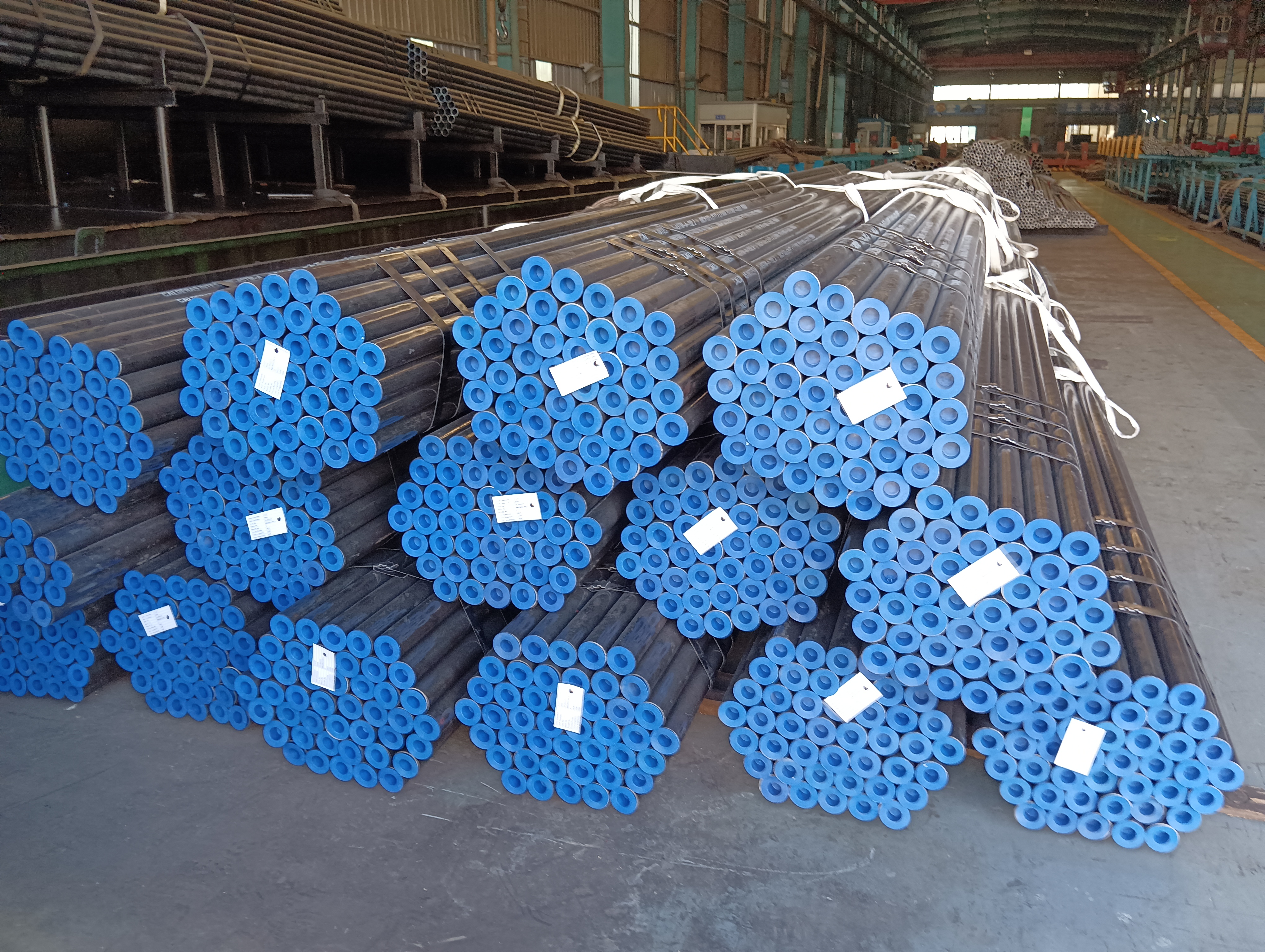 Seamless heat-exchanger tube bundles with protective end caps and ID tags, from a ZC ASTM A192 supply to South America.
What we have seen on operating projects: On a gas compression station in the Middle East, the project equipment datasheet specified air-cooled heat exchangers at 8 FPI. The specification was based on the original project site survey, which classified the environment as "moderate industrial." Within 2 operating seasons, the inter-fin gaps had accumulated sand and dust deposits bridging between adjacent fins. Air-side pressure drop across the bundle had increased by 45%, reducing fan airflow and dropping thermal performance by 35% from the clean-condition rating. Bundle cleaning required crane removal and hydroblasting — every 14 months. A 4–5 FPI specification would have extended the cleaning interval to 3–4 years and allowed in-situ hosing without bundle removal. The 4 FPI fin pitch costs the same at the mill; the 8 FPI choice cost 4 additional crane lifts and 4 additional cleaning campaigns over 5 years.
What is Fin Pitch?
Fin pitch is expressed as either:
- Fins per inch (FPI): the number of fin turns per inch of finned tube length — the most common convention in API 661 and North American practice
- Fins per metre (FPM): equivalent metric expression used in IEC and European specifications
- Fin spacing (mm): the gap between adjacent fin faces, measured centre-to-centre (pitch) or face-to-face (clear spacing)
The relationship between these expressions:
- 1 FPI = 39.37 FPM
- Fin pitch in mm = 25.4 / FPI
Common finned tube pitches and their typical applications:
| Fin Pitch (FPI) | Fin Pitch (FPM) | Inter-Fin Spacing (mm approx.) | Typical Application |
|---|---|---|---|
| 3 | 118 | ~6.0 | Very fouling air (desert, coastal) |
| 4 | 157 | ~4.5 | Moderately dusty environments |
| 5 | 197 | ~3.6 | Standard outdoor industrial service |
| 6 | 236 | ~2.9 | Moderate duty, clean air |
| 8 | 315 | ~2.1 | Clean air, controlled environment |
| 10 | 394 | ~1.6 | Clean air, refrigeration, HVAC |
| 12 | 472 | ~1.2 | Very clean air, high-duty |
Inter-fin spacing values assume a fin thickness of 0.41 mm (0.016") aluminum. Actual values vary with fin thickness.
How Fin Pitch Affects Heat Transfer
Surface Area per Unit Length
Higher fin pitch packs more fins per metre of tube, increasing the total external surface area per metre. The relationship is approximately linear within practical FPI ranges. For a 25.4 mm OD bare tube with 12.7 mm (½ inch) fin height:
| Fin Pitch (FPI) | External Area per Metre (m²/m, approx.) |
|---|---|
| 3 | ~0.35 |
| 5 | ~0.48 |
| 8 | ~0.60 |
| 10 | ~0.66 |
| 12 | ~0.70 |
Values are approximate and depend on fin height, thickness, and bond type.
The gain in surface area with increasing FPI follows a diminishing returns curve: going from 3 to 6 FPI doubles the fin count per metre but adds proportionally less area because the inter-fin spaces become smaller and fin tip area becomes a larger fraction of the total fin area.
Air-Side Heat Transfer Coefficient
The air-side (or gas-side) heat transfer coefficient is a function of the air velocity, air properties, and the geometry of the fin array. For a given face velocity (air velocity at the bundle face), higher fin pitch increases air velocity in the inter-fin channels — because the same volume flow passes through a smaller free-flow area. Higher local velocity in the channels increases the heat transfer coefficient on the fin surfaces. However, the improvement in coefficient partially offsets the gain in area: a 50% increase in fin pitch produces a 15–25% increase in heat transfer coefficient but at the cost of a much larger increase in pressure drop. The net effect on heat duty depends on which resistance is controlling.
For the complete boiler tube grade mechanical properties and surface area reference data, see the ASME Boiler Tube Spec Tables →
To convert between FPI and FPM, or between mm and inch fin dimensions, use the Unit Converter →
How Fin Pitch Affects Air-Side Pressure Drop
Air-side pressure drop across a finned tube bundle is the dominant operating cost driver in air-cooled heat exchangers. Fan power is proportional to flow rate multiplied by pressure drop across the bundle.
The Fanning friction factor for flow through fin arrays increases rapidly as the inter-fin channel narrows (i.e., as fin pitch increases). Empirical correlations for finned tube pressure drop (such as those in the HTRI Xchanger Suite or HTFS ACOL methods) show that for typical air cooler geometries:
- Doubling fin pitch from 4 to 8 FPI at constant face velocity approximately doubles or triples the air-side pressure drop
- Increasing from 6 to 12 FPI at constant face velocity approximately triples pressure drop
Pressure drop also depends on the number of tube rows, tube pitch (longitudinal and transverse), and fin geometry. A four-row bundle at 8 FPI may have air-side pressure drop of 50–100 Pa at a face velocity of 2.5 m/s. A three-row bundle at 5 FPI in the same application may have 25–50 Pa.
Practical implication: Equipment designers in hot climates often specify lower fin pitches (4–6 FPI) with more tube rows to hold pressure drop and fan power within limits, instead of using high fin pitch to reduce bundle size. The economic optimum depends on the site power cost, ambient temperature, and project capital budget.
Fouling in an air-cooled heat exchanger is a self-accelerating process, not a linear one. As dust deposits accumulate between fins, the free-flow area decreases; the same fan delivers less air volume through the higher-resistance bundle. Lower air velocity means the entering particles are no longer swept through the bundle — they settle more readily. The bundle that was designed for self-cleaning by air velocity at 2.5 m/s face velocity now operates at 1.8 m/s face velocity because of its own fouling. At that lower velocity, deposition rate accelerates. A fin pitch that is marginally too high for the site dust concentration will reach this runaway fouling threshold faster than a clean-site analysis would predict — and the performance collapse is faster than proportional to the degree of fouling.
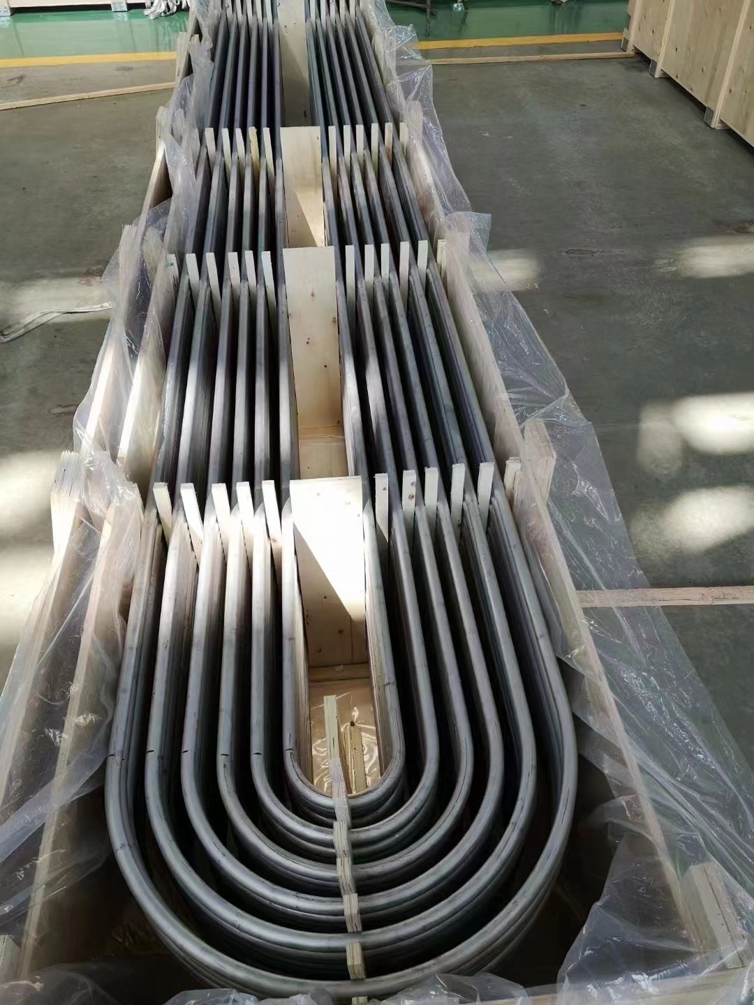 U-bend heat-exchanger tube bundles crated for export shipment.
Fouling, Fin Spacing, and Cleanability
Fouling is the accumulation of deposits — dust, sand, salt crystals, insect debris, or hydrocarbon films — on the air-side fin surfaces. Fouling blocks the inter-fin channels, increases air-side pressure drop, and reduces heat transfer performance.
The minimum inter-fin clear spacing governs cleanability:
- Below 2 mm clear spacing (above ~10 FPI for standard fins): manual cleaning is very difficult; pressurised water jetting may be unable to penetrate all inter-fin gaps; bundle removal and mechanical cleaning may be required
- 2–4 mm clear spacing (5–10 FPI): water jetting or air blasting from the bundle face can partially clean the fins; not effective for compacted deposits
- Above 4 mm clear spacing (3–5 FPI for standard fins): effective water jetting; manual brush cleaning feasible; walking-beam cleaning machines can sweep between fins
For sites with dusty or sandy air — common in Middle East, North Africa, the Arabian Peninsula, and the Atacama-adjacent regions of South America — API 661 recommends a minimum fin pitch of 3–4 FPI. ZC Steel Pipe's ACHE fin tubes for these markets are typically supplied at 4–5 FPI with HFRW carbon steel fins for durability in cleaning cycles.
Fin Surface Efficiency
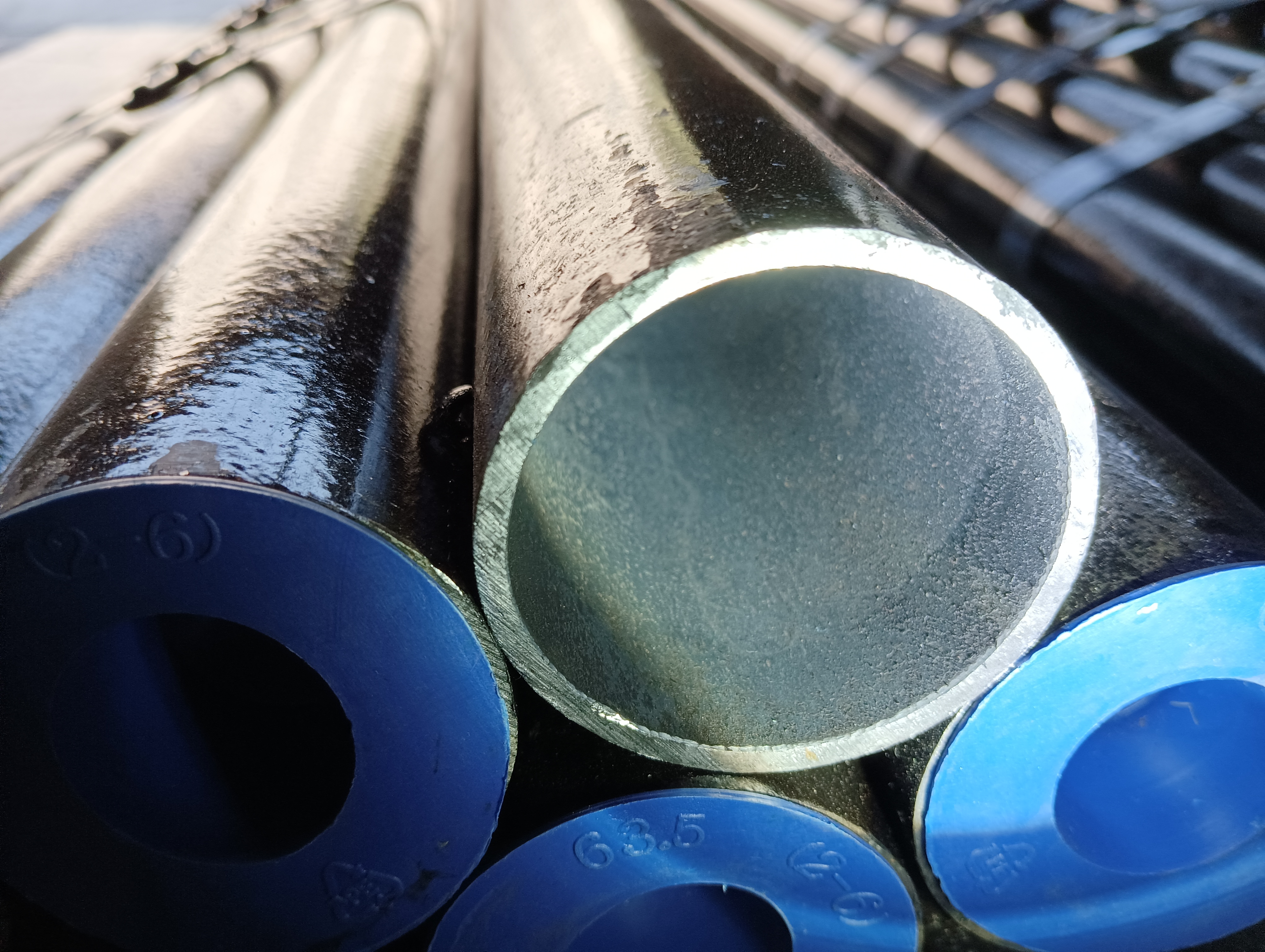 Close-up of a seamless heat-exchanger tube end with a clean, bright bore.
Fin Efficiency (η_f)
Fin efficiency is defined as:
η_f = tanh(mL) / (mL)
Where:
- m = √(2h / (k_f × t_f)) is the fin parameter
- h = air-side heat transfer coefficient (W/m²·K)
- k_f = fin material thermal conductivity (W/m·K)
- t_f = fin thickness (m)
- L = fin height (m) — or corrected fin height accounting for tip heat transfer
For typical air cooler conditions (h ≈ 40 W/m²·K, aluminum fins, L = 12.7 mm):
- Aluminum (k = 205 W/m·K): η_f ≈ 0.91–0.95
- Carbon steel (k = 50 W/m·K): η_f ≈ 0.72–0.80
- Stainless steel (k = 16 W/m·K): η_f ≈ 0.55–0.65
These are indicative values for standard fin geometries. Calculate η_f for your specific geometry using the applicable correlation.
Worked Example: Fin Efficiency for Aluminum vs Carbon Steel Fins
Using the formulas above, the following calculation demonstrates the difference in fin efficiency between aluminum and carbon steel fins for identical fin geometry and operating conditions.
Conditions: h = 40 W/m²·K (air-side heat transfer coefficient), fin height L = 12.7 mm = 0.0127 m
Step 1 — Fin parameter m for aluminum fins (k = 205 W/m·K, t = 0.41 mm = 0.00041 m):
m = √(2h / (k_f × t_f)) = √(2 × 40 / (205 × 0.00041)) = √(80 / 0.0841) = √951 = 30.8 m⁻¹
mL = 30.8 × 0.0127 = 0.391
η_f (aluminum) = tanh(0.391) / 0.391 = 0.373 / 0.391 = 0.954
Step 2 — Fin parameter m for carbon steel fins (k = 50 W/m·K, t = 0.89 mm = 0.00089 m):
m = √(2 × 40 / (50 × 0.00089)) = √(80 / 0.0445) = √1798 = 42.4 m⁻¹
mL = 42.4 × 0.0127 = 0.538
η_f (carbon steel) = tanh(0.538) / 0.538 = 0.490 / 0.538 = 0.911
Step 3 — Overall surface efficiency (assuming A_f/A_total = 0.88):
η₀ (aluminum) = 1 − 0.88 × (1 − 0.954) = 1 − 0.88 × 0.046 = 1 − 0.040 = 0.960
η₀ (carbon steel) = 1 − 0.88 × (1 − 0.911) = 1 − 0.88 × 0.089 = 1 − 0.078 = 0.922
At the same fin geometry, aluminum achieves η₀ = 0.960 and carbon steel achieves η₀ = 0.922 — a 4-percentage-point difference. In a re-tubing project replacing extruded aluminum fins with HFRW carbon steel fins at the same pitch and height, thermal performance will be approximately 4–5% lower unless fin height is reduced (to keep mL low and η_f high) or face velocity is increased. The heat transfer calculation must be redone for the replacement material; it cannot be assumed equal.
Overall Surface Efficiency (η_0)
Overall surface efficiency accounts for both the fin area and the unfinned tube area between fins:
η_0 = 1 − (A_f / A_total) × (1 − η_f)
Where:
- A_f = total fin surface area per tube length (m²/m)
- A_total = total external surface area per tube length including fins and bare inter-fin tube area (m²/m)
For a well-designed finned tube with aluminum fins, the finned area fraction (A_f / A_total) is typically 0.85–0.90, meaning 85–90% of the total external area is fin surface. If η_f = 0.92, then η_0 ≈ 1 − 0.87 × (1 − 0.92) = 1 − 0.070 = 0.93. For carbon steel fins with η_f = 0.75, η_0 ≈ 1 − 0.87 × (1 − 0.75) = 0.78.
The difference in η_0 between aluminum and carbon steel fins is significant for the overall heat transfer coefficient. A bundle designed with aluminum fins that is re-tubed with carbon steel fins at the same fin pitch will deliver lower performance unless compensated by adding tube rows or reducing face velocity.
Recommended Fin Pitches by Application
| Application | Environment | Recommended Pitch | Bond Type |
|---|---|---|---|
| Refinery process air cooler (HC service) | Moderate to dusty | 5–6 FPI | HFRW steel fins |
| Refinery process air cooler (extreme dust) | Desert/coastal | 3–4 FPI | HFRW steel fins |
| Gas plant trim cooler | Moderate | 6–8 FPI | HFRW steel fins |
| Lube oil cooler | Clean/moderate | 6–8 FPI | Extruded aluminum |
| Instrument/utility air cooler | Clean | 8–10 FPI | Extruded aluminum |
| Fired heater convection section economiser | Flue gas (fouling) | 3–5 FPI | HFRW steel fins |
| HVAC coils | Indoor/clean | 10–14 FPI | Plate fins or crimped |
| Shell-and-tube HX (low-fin) | Shell-side liquid | 19 FPI | Integral machined |
The table above reflects the application and site conditions that drive pitch selection. The cleanability thresholds discussed in the fouling section should be the binding constraint: if the site environment places a bundle in the "dusty" or "coastal" row, use the pitch from that row regardless of what a compact-design optimisation might suggest.
When NOT to Specify High Fin Pitch (>8 FPI)
High fin pitch (8–12 FPI) delivers the most area in the smallest bundle footprint, but it is only appropriate for clean-air sites with in-place bundle washing capability. The following site conditions disqualify 8+ FPI:
| Site condition | Maximum recommended FPI | Reason |
|---|---|---|
| Desert or sandy environment (Middle East, North Africa, Saharan Africa) | 3–4 FPI | Dust bridging blocks narrow inter-fin gaps irreversibly; 3 FPI allows in-situ hosing |
| Coastal or offshore (salt-laden air, tropical humid) | 4–5 FPI | Salt crystals and biological fouling block fine gaps; corrosion of fin tips narrows the effective gap further |
| Petrochemical plant with airborne hydrocarbon mists | 4–6 FPI | Hydrocarbon films bind dust to fin surfaces, forming cohesive plugs in fine-pitch bundles |
| Industrial site with heavy particulates (cement plant, quarry) | 3–4 FPI | Cement dust compacts between fins rapidly and requires mechanical removal |
| Service requiring in-situ cleaning without crane | 5 FPI max | Below 2 mm inter-fin clear spacing, water jetting cannot penetrate the full bundle depth |
| Application with seasonal fouling (monsoon, harmattan) | 4–5 FPI | Performance must be recoverable after cleaning by simple in-situ methods during outage window |
The inter-fin clear spacing at 8 FPI for a 0.41 mm aluminum fin is approximately 2.1 mm. That is below the threshold at which a standard water jet can reliably penetrate to the back of a multi-row bundle. Operators who specify 8 FPI expecting to clean with in-situ hosing will be disappointed at the first cleaning interval.
Fin Pitch Selection Failure Modes to Specify Against
Failure Mode 1 — Over-specified fin pitch for dusty site environment
Mechanism: An 8 FPI bundle installed in a gas processing plant in a dust-prone environment has a clean inter-fin clear spacing of 2.1 mm. During the dry season, fine particulate matter (median particle diameter 20–80 µm) enters the bundle and deposits on fin surfaces. Within 8 months, the effective clear spacing drops to 1.4 mm; by 14 months, bridging deposits form across the full fin gap at multiple locations. Fan airflow drops 30% due to increased air-side resistance; thermal performance drops 35%. Bundle requires crane removal and hydroblasting to restore clean-condition performance.
Diagnostic: Monitor increasing air-side pressure drop at the fan diffusers (before and after bundle). Visual inspection of the bundle face shows progressive closure of the fin gaps — a flashlight shone perpendicular to the bundle face should show light passing through; if not, the gaps are bridged.
Fix: Re-tube with a 4 FPI bundle at the next planned outage. Specify 4 FPI on the replacement PO with the note "site environment: dusty, harmattan season." Add in-situ bundle cleaning to the annual maintenance schedule: hosing at 6–8 months, full inspection at 12 months.
Failure Mode 2 — Re-tubing with different FPI without recalculating air-side pressure drop
Mechanism: A 6 FPI bundle is replaced with an 8 FPI bundle to increase thermal capacity on the assumption that more fins means more area means more duty. The new bundle has 33% more fins per metre and a higher air-side pressure drop. The existing fan motors were sized for the 6 FPI bundle resistance. At the 8 FPI bundle's higher pressure drop, the fans deliver 15% less airflow at the same motor power — which reduces the actual heat transfer coefficient on the air side and partially cancels the area gain. The actual capacity increase is only 8% rather than the expected 20%.
Diagnostic: Post-startup performance test shows less thermal capacity improvement than the re-tube specification predicted. Fan motor current measurements confirm fans are operating near the stall point of their performance curve.
Fix: Recalculate air-side pressure drop for the new fin pitch before approving the re-tube specification. If the existing fan motors cannot accommodate the higher pressure drop, either stay at 6 FPI (adding tube rows instead to increase capacity) or specify new fan motors rated for the 8 FPI resistance.
Failure Mode 3 — Fouling resistance underestimated for local site conditions
Mechanism: An air cooler specified and rated using a standard API 661 fouling resistance factor (h = 0.0002 m²·K/W on the air side) is installed at a plant located downwind of an asphalt processing unit where volatile hydrocarbon mists are present in the ambient air. Hydrocarbon mists deposit on the fin surfaces and act as a binding agent for dust, forming cohesive deposits with an effective fouling resistance of 0.0008–0.0010 m²·K/W — 4–5× the design assumption. The air cooler falls below minimum duty within 18 months despite the design fouling allowance.
Diagnostic: Thermal performance short-fall appears on the first performance test after the initial fouling accumulation period (typically 3–6 months in high-fouling environments). The air-side fouling resistance can be back-calculated from the overall U coefficient deficit: 1/U_actual − 1/U_clean = total additional resistance, of which the air-side fouling is the largest component.
Fix: Specify site-specific fouling resistance based on actual site dust and mist characterisation — not the API 661 standard factor — for plants adjacent to heavy fouling sources. Use wider fin pitch (4–5 FPI) and schedule 6-monthly cleaning regardless of thermal performance trend. ZC Steel Pipe can supply pre-calculated bundle performance at site-specific fouling conditions based on the customer's site characterisation data.
Purchase Order Guidance
Fin pitch must be specified on the equipment datasheet and confirmed on the fin tube manufacturer's dimensional drawing. Key items to verify:
- Fin pitch in FPI and the equivalent mm pitch
- Fin height in mm (measured from tube OD to fin tip)
- Fin thickness at the root and tip in mm
- Resulting finned OD — confirm it fits within the bundle header hole pattern
- Inter-fin clear spacing in mm — confirm it meets project fouling and cleanability requirements
Procurement trap — specifying area without specifying pitch:
Wrong PO: "Air-cooled heat exchanger, 500 m² total external fin surface, 6-tube-row bundle, API 661."
What ships: The supplier selects 10 FPI with 12.7 mm fin height to deliver 500 m² in a compact 4-row bundle using fewer tubes — lower fabrication cost, smaller footprint. The 10 FPI bundle passes the surface area criterion and fits the header hole pattern. The site is a gas plant in Northern Nigeria with harmattan dust season. Within one dry season the bundle is fouled past recovery by in-situ methods.
Correct PO: "Air-cooled heat exchanger, minimum heat duty [MW] at [inlet/outlet temperatures], API 661. Maximum fin pitch: 5 FPI for this site (dusty service, per site survey report [reference]). Inter-fin clear spacing not less than 3.5 mm. Bundle design to allow in-situ water jetting cleaning without crane removal." Specify both the required heat duty AND the maximum allowable fin pitch for the site environment.
Procurement trap — thermal rating at clean conditions only: Air-cooled heat exchanger ratings are often based on clean, unfouled surface area using a fouling factor as an allowance. In extreme fouling environments, the actual fouling resistance may exceed the design fouling factor within one or two years of operation, causing the unit to fall short of capacity. For high-fouling sites, specify wide fin pitch, design for a cleaning interval of 6–12 months, and verify that the bundle can be cleaned in-situ without crane removal. ZC Steel Pipe can supply fin tubes with wide pitches (3–4 FPI) and robust HFRW bonds specifically for challenging site environments.
Frequently Asked Questions
What is fin pitch in a heat exchanger?
Fin pitch is the number of fins per unit of tube length. It is expressed in fins per inch (FPI) or fins per metre (FPM). A fin pitch of 6 FPI means there are six complete fin turns for every inch (25.4 mm) of finned tube length. Fin pitch determines the spacing between adjacent fins and therefore controls air-side pressure drop, air-side heat transfer coefficient, and the surface area available for heat transfer per unit of tube length. Higher fin pitch increases surface area but also increases pressure drop and reduces the gap between fins, making the tube bundle more prone to fouling and harder to clean.
What fin pitch should I specify for a dusty or sandy environment?
In dusty or sandy environments — typical of Middle East, North Africa, and onshore Australia sites — a low fin pitch of 3 to 5 fins per inch (118 to 197 FPM) is recommended. Wide inter-fin spacing allows particulates to pass through the bundle without bridging between fins and blocking airflow. At 3–4 FPI, the fin gap is large enough that routine hosing or air blasting can clean between the fins without removing the bundle. Higher pitches of 8–12 FPI accumulate blockages rapidly in dusty service, causing progressive loss of cooling capacity that may not be immediately visible unless air-side pressure drop is monitored continuously.
How does fin height affect heat exchanger efficiency?
Fin efficiency (η_f) decreases as fin height increases. Longer fins experience a greater temperature gradient from fin root to fin tip — the tip is cooler than the root because heat must conduct along the fin length before transferring to the air. For a given fin material and base tube temperature, doubling the fin height reduces fin efficiency because the thermal resistance along the fin length increases. In practice, aluminum fins remain highly efficient (η_f > 85%) for heights up to about 15 mm due to aluminum's high thermal conductivity. Carbon steel fins of the same height have lower efficiency (η_f typically 60–80%) because steel conducts heat approximately four times less effectively than aluminum.
What is fin efficiency and overall surface efficiency?
Fin efficiency (η_f) is the ratio of the actual heat transfer from a fin to the heat that would be transferred if the entire fin surface were at the base (tube wall) temperature. A perfect fin with infinite conductivity would have η_f = 1.0. Real fins have η_f < 1.0 because the fin temperature drops from root to tip as heat must conduct along the fin to reach the tip. Overall surface efficiency (η_0) is the area-weighted average efficiency of the entire external surface of the tube — it accounts for both the fin area with its fin efficiency and the bare tube area between fins with η = 1.0. Overall surface efficiency is used in the LMTD or NTU heat transfer calculation as: η_0 = 1 − (A_f/A_total) × (1 − η_f).
What is the effect of fin pitch on air-side pressure drop?
Air-side pressure drop increases significantly as fin pitch increases. At a constant face velocity, reducing the fin gap by doubling the fin pitch roughly doubles the friction factor contribution from the inter-fin channels and increases pressure drop by a factor of 2 to 3. Higher pressure drop increases fan power consumption and may require larger fan motors or additional fan bays. In an air-cooled heat exchanger, fan power typically represents 1–3% of the process duty recovered, but in optimised designs with high fin pitch, fan power can become a meaningful operating cost. Equipment designers balance fin pitch against fan power in an economic optimisation that accounts for fin pitch, tube rows, bundle length, and capital cost.
Can fin pitch be changed when re-tubing an existing air-cooled heat exchanger?
Yes, fin pitch can be changed when re-tubing, within the constraint that the finned OD of the new tube must still fit within the existing tube bundle header and support plate holes. Increasing fin pitch on re-tubing can increase capacity if the original bundle was under-finned for the available fan power. Decreasing fin pitch improves fouling resistance if the site has become dustier since the original design. Any change in fin pitch changes the air-side pressure drop and the heat transfer area per tube, which must be recalculated to confirm the new bundle meets the original heat duty specification at the available air flow rate. ZC Steel Pipe can supply replacement fin tube bundles to the same or revised fin pitch on a datasheet-by-datasheet basis.
What fin pitch is typical for shell-and-tube heat exchangers?
Shell-and-tube heat exchangers use low-fin tubes with integral fins machined or rolled from the tube wall. Typical low-fin pitches are 19 fins/inch (748 FPM) with fin heights of 1.0–1.6 mm (0.040–0.063 inch). This fine pitch and shallow fin height keep the shell-side pressure drop within acceptable limits while providing 2.5 to 3.5 times more shell-side surface area than a bare tube of the same OD. The TEMA Standards (latest edition) specify dimensional tolerances and material grades for low-fin tubes used in TEMA shell-and-tube exchangers.
How does fin material conductivity affect which fin pitch to select?
Higher-conductivity fin materials (aluminum at 205 W/m·K) maintain high fin efficiency at longer fin heights and finer pitches than lower-conductivity materials (carbon steel at 50 W/m·K). With aluminum fins, a designer can specify a fine pitch (8–10 FPI) and tall fins (12–15 mm) and still achieve overall surface efficiency above 80%. With carbon steel fins, the same dimensions would give lower fin efficiency, and the designer may need to reduce fin height or use a coarser pitch to recover efficiency. When switching from aluminum to steel fins in a re-tubing project, the heat transfer calculation must be redone with the corrected fin efficiency to confirm that the replacement bundle still meets the design duty.