
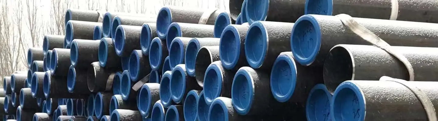
LSAW (Longitudinal Submerged Arc Welded) steel pipe is the standard pipe type for large-diameter high-pressure oil and gas transmission pipelines globally. Its combination of heavy wall capability, single longitudinal weld, and tight dimensional tolerances makes it the only practical choice for pipelines from 16 inches to 60 inches OD where SSAW's helical weld geometry is unacceptable and seamless pipe is unavailable at the required diameter. For offshore and subsea projects, LSAW is the dominant pipe type specified in project standards.
ZC Steel Pipe manufactures and supplies LSAW pipe to API Specification 5L, 46th Edition in grades X52 through X80 PSL2, covering OD 406 mm to 1219 mm (16 to 48 inches). Our production includes 3LPE, FBE, and concrete weight coated pipe for onshore and offshore transmission pipeline projects in Africa, the Middle East, South America, and Southeast Asia, with EN 10204 3.1 and 3.2 documentation and third-party inspection.
At a Glance
LSAW (Longitudinal Submerged Arc Welded) pipe is the standard choice for large-diameter, high-pressure oil and gas transmission — the range where SSAW's helical seam is unacceptable and seamless is unavailable. It is formed from plate by the JCOE press sequence, welded inside and outside (DSAW), then cold-expanded for roundness and residual-stress control, and supplied almost exclusively as PSL2.
| Attribute | LSAW pipe |
|---|---|
| Standard | API 5L, 46th Edition, PSL2 |
| OD range | 406–1524 mm (16–60"); ZC 406–1219 mm (16–48") |
| Wall range | ~6–50 mm |
| Common grades | X52, X60, X65, X70, X80 (all PSL2) |
| Delivery condition | M (TMCP) for X65 and above |
| Forming | JCOE (wide OD range) or UOE (tightest ovality) |
| Weld NDT | 100% AUT of the seam, before and after cold expansion |
The one PO line most often left blank is the Charpy V-notch test temperature — set it to your minimum design temperature, not the API 5L 0°C default. Full grade data is in the API 5L specification tables and pipe dimensions in the ASME B36.10M schedule chart; MAOP and hydrotest pressure size the wall in the Pipeline Design Calculator.
The most consistently missing item on LSAW purchase orders across Africa and the Middle East is the Charpy V-notch test temperature. API 5L PSL2 requires Charpy testing but allows the purchaser to specify the temperature and minimum energy — if neither is stated, the mill tests at the API 5L default of 0°C at 40 J. On projects in the Gulf of Guinea where seabed temperatures are 4–8°C and the hydrostatic test is conducted at ambient during the cold season (10–15°C), this is borderline adequate. On projects in the East African Rift Valley at 2,000 m elevation where night temperatures fall to −5°C, it is not. We have seen pipe arrive on site with Charpy test records at 0°C when the project specification required −10°C. The mill cannot retest after the pipe is manufactured without cutting new specimens — which is destructive sampling on a limited number of joints. State the Charpy temperature on every LSAW PO. This is not optional detail.
What Is LSAW Pipe?
LSAW steel pipe is manufactured from rolled steel plate that is formed into a cylinder and welded along one longitudinal seam. The weld process is submerged arc welding (SAW), in which the welding arc burns beneath a blanket of granular flux — the flux shielding the arc and weld pool from atmospheric contamination produces a very clean, high-quality weld with minimal porosity and consistent mechanical properties.
LSAW is manufactured exclusively from plate, not coil. This is fundamental to its large-diameter capability: plate can be produced in thicknesses and widths that coil cannot achieve, enabling heavy-wall LSAW pipe that ERW — which uses coil feed — cannot match. The plate specification for LSAW is typically ASTM A36, ASTM A572, or equivalent hot-rolled HSLA plate rolled to the chemical and mechanical requirements of the API 5L grade being produced.
For a comparison of LSAW, ERW, and SSAW pipe types in the context of pipeline project selection, see the Welded Steel Pipe: ERW, LSAW and SSAW Guide →
JCOE Manufacturing Process — Step by Step
The JCOE process is the dominant forming sequence for LSAW pipe from 16-inch to 60-inch OD. The name describes the sequence of forming shapes applied to the plate before welding.
Step 1 — Plate Preparation
Steel plate cut to the required width (which determines the pipe circumference) and length (which determines pipe length, typically 12 m or 18 m joint). The plate edges are machined by a milling machine to precise bevels for optimal SAW weld penetration. Plate edges are also ultrasonically tested at this stage to detect laminations.
Step 2 — J-Forming (Edge Crimping)
A hydraulic press crimps the two long edges of the plate into a J-profile. This pre-bend prevents flat spots at the weld seam area and ensures the plate edges align correctly when the pipe is closed.
Step 3 — C-Forming (Progressive Bending)
A series of press strokes bend the plate progressively into a C-shape, working from the edges toward the centre. Each stroke covers a portion of the plate width. This incremental process allows a single press to form a wide range of pipe diameters without dedicated tooling for each size.
Step 4 — O-Forming (Closing)
A final pressing step closes the C-shape into a nearly circular O cross-section. The pipe is then tack-welded along the seam to hold its shape before the main welds are deposited.
Step 5 — Inside Submerged Arc Welding (ISAW)
The tack-welded pipe is placed on a welding fixture and the inside weld is deposited in one or more passes by a SAW torch running inside the pipe bore. The flux blanket covers the inside of the seam. The inside weld penetrates approximately two-thirds of the wall thickness.
Step 6 — Outside Submerged Arc Welding (OSAW)
The pipe is repositioned and the outside weld is deposited in one or more passes by a SAW torch running on the outside of the pipe. The inside and outside welds together produce a full-penetration weld meeting API 5L requirements for DSAW (Double Submerged Arc Welded) pipe.
For OD above 323.9 mm (12.750 inches), API 5L requires both inside and outside weld passes — this is the DSAW requirement. All commercial LSAW pipe in the standard size range therefore satisfies this requirement by default.
Step 7 — Mechanical Cold Expansion (E-Expanding)
The welded pipe is expanded by approximately 0.8–1.5% of its circumference using a mechanical expander with segmented dies. Expansion achieves two objectives: it improves roundness and ovality to within API 5L tolerance, and it introduces uniform compressive pre-stress in the weld zone that improves fatigue resistance. After expansion, the pipe OD and wall thickness are measured and recorded for the dimensional test report.
The mechanical cold expansion step at 0.8–1.5% OD increase is not primarily a dimensional correction — it is a residual stress management step. The JCOE forming process leaves compressive residual stresses in the pipe body from the plate bending, and tensile residual stresses at the weld seam from weld solidification contraction. When the pipe is expanded, both residual stress profiles are modified: the body residual stress distribution becomes more uniform, and the weld seam tensile residual stress is partially relaxed by the plastic deformation. This has two practical consequences: it improves the roundness of the pipe (the dimensional benefit), and it reduces the tensile residual stress at the weld seam that would otherwise accelerate fatigue crack growth under cyclic pressure loading. Cold expansion is specified on offshore LSAW pipe for both reasons, not just the first one.
For the API 5L specification tables covering grades, mechanical properties, and delivery conditions, see the API 5L Specification Tables →
UOE Process — The Alternative for Offshore Pipe
The UOE (U-press, O-press, Expansion) process is used at dedicated large-diameter pipe mills producing primarily offshore-quality pipe. The forming sequence differs from JCOE:
U-pressing: The plate is bent into a deep U-shape by a single large press with a mandrel die.
O-pressing: A second large press closes the U into an O cross-section in a single stroke, producing very consistent roundness.
Welding and Expansion: Inside and outside SAW welding followed by hydraulic (not mechanical) expansion to the final OD.
| Criterion | JCOE | UOE |
|---|---|---|
| Forming method | Multiple incremental press strokes | Two large dedicated presses |
| Roundness control | Good | Excellent — tighter ovality tolerances |
| Capital requirement | Moderate | Very high |
| OD flexibility | Wide range on same press | Typically dedicated to narrower OD range |
| Primary market | Onshore and offshore transmission | Offshore, subsea, reel-lay |
For offshore projects governed by DNV-ST-F101, UOE pipe may be preferred by project specifications for its tighter dimensional tolerances. Confirm the pipe manufacturing process (JCOE or UOE) in the MRQ if the project specification requires UOE.
API 5L Grades for LSAW Pipe
LSAW pipe is supplied exclusively in PSL2 for all transmission pipeline projects. PSL2 adds mandatory Charpy V-notch impact testing, chemistry control (carbon equivalents CE IIW and Pcm), and a yield-to-tensile (Y/T) ratio limit of 0.93 compared to PSL1.
The M delivery condition (TMCP — Thermo-Mechanical Controlled Processing) is standard for X65, X70, and X80 LSAW because controlled rolling of the parent plate is the method used to achieve the required combination of yield strength, toughness, and weldability without the high carbon equivalent that would otherwise be required.
PSL2 mechanical properties for common LSAW grades (API 5L, 46th Edition):
| Grade | Min Yield | Max Yield | Min Tensile | Max Y/T |
|---|---|---|---|---|
| L360 / X52 | 360 MPa (52,200 psi) | 530 MPa (76,900 psi) | 460 MPa (66,700 psi) | 0.93 |
| L415 / X60 | 415 MPa (60,200 psi) | 565 MPa (81,900 psi) | 520 MPa (75,400 psi) | 0.93 |
| L450 / X65 | 450 MPa (65,300 psi) | 600 MPa (87,000 psi) | 535 MPa (77,600 psi) | 0.93 |
| L485 / X70 | 485 MPa (70,300 psi) | 635 MPa (92,100 psi) | 570 MPa (82,700 psi) | 0.93 |
| L555 / X80 | 555 MPa (80,500 psi) | 705 MPa (102,300 psi) | 625 MPa (90,600 psi) | 0.93 |
Source: API Specification 5L, 46th Edition, Table 7. Y/T limit applies when OD > 323.9 mm (12.750 in).
For pipeline design calculations using ASME B31.8, use the Pipeline Design Calculator →
Chemistry control for LSAW grades (X65M PSL2 representative):
| Element | Limit (X65M, PSL2) |
|---|---|
| Carbon (C) max | 0.12% |
| Manganese (Mn) max | 1.60% |
| Phosphorus (P) max | 0.025% |
| Sulfur (S) max | 0.015% |
| Nb+V+Ti combined max | 0.15% |
| CE IIW max | 0.43 |
| CE Pcm max | 0.25 |
Source: API Specification 5L, 46th Edition, Table 5 (L450M / X65M chemistry, TMCP delivery condition).
Hydrostatic Test Pressure — Worked Calculation
API 5L calculates the required hydrostatic test pressure using the nominal (specified) wall thickness, not the minimum. The formula for PSL2 is:
P_test = 2 × SMYS × t × f / D
Where f is the fraction of SMYS at which the test is conducted. API 5L permits f up to 0.90 (90% SMYS) for PSL2.
Example: 24-inch (609.6 mm OD) LSAW, nominal wall 14.3 mm
| Grade | SMYS (MPa) | P_test at 90% SMYS (MPa) | P_test (psi) | ASME B31.8 Class 1 MAOP (MPa) | Test-to-MAOP Ratio |
|---|---|---|---|---|---|
| X65M PSL2 | 450 | 2 × 450 × 14.3 × 0.90 / 609.6 = 19.0 MPa | 2,757 psi | 2 × 450 × 14.3 × 0.72 / 609.6 = 15.2 MPa | 1.25× |
| X70M PSL2 | 485 | 2 × 485 × 14.3 × 0.90 / 609.6 = 20.5 MPa | 2,972 psi | 2 × 485 × 14.3 × 0.72 / 609.6 = 16.4 MPa | 1.25× |
ASME B31.8 Class 1 design factor F = 0.72. Nominal wall 14.3 mm used for both calculations.
The PSL2 hydrostatic test pressure (19.0 MPa for X65M) is 25% above the ASME B31.8 Class 1 design MAOP (15.2 MPa). This margin is intentional: the hydrostatic test at 90% SMYS also serves as a proof test of the weld seam. Any undetected weld defect capable of failing at operating pressure would be expected to open or propagate at this test pressure, making the hydrostatic test the final quality gate for the weld seam in service.
Use the Pipeline Design Calculator → for project-specific MAOP and hydrostatic test pressure calculations.
Standard Sizes and Dimensional Tolerances
Standard OD and wall thickness range for JCOE LSAW:
| OD (inches) | OD (mm) | Typical Wall Range (mm) | Common API 5L Grades |
|---|---|---|---|
| 16 | 406.4 | 6.4–25.4 | X52–X70 PSL2 |
| 18 | 457.2 | 7.1–28.6 | X52–X70 PSL2 |
| 20 | 508.0 | 7.9–31.8 | X52–X70 PSL2 |
| 24 | 609.6 | 7.9–38.1 | X60–X80 PSL2 |
| 30 | 762.0 | 9.5–38.1 | X60–X80 PSL2 |
| 36 | 914.4 | 9.5–40.0 | X65–X80 PSL2 |
| 42 | 1066.8 | 11.1–40.0 | X65–X70 PSL2 |
| 48 | 1219.2 | 12.7–40.0 | X65–X70 PSL2 |
API 5L dimensional tolerances for LSAW pipe (PSL2, D > 508 mm):
| Parameter | Tolerance |
|---|---|
| OD at pipe body | ±0.5% of specified OD |
| OD at pipe ends | ±1.6 mm for D ≤ 508 mm; ±0.4% for D > 508 mm |
| Wall thickness (t) min | ≥ 0.875 × t_specified |
| Out-of-roundness (OD range) | ≤ 0.6% of specified OD for D > 508 mm |
| Straightness | ≤ 0.2% of total pipe length |
A 28″ LSAW order in the real size range: The 16–48″ JCOE range in these tables is where our LSAW orders actually fall. A recent supply to Africa ran 350 pieces of 28″ (711 mm) X52M PSL2 LSAW at 12.7 mm wall, finished with 3LPE plus a concrete weight coating of 70 mm minimum for negative buoyancy. The M-condition delivery is what makes the girth-weldability work at that diameter — X52M's low carbon keeps the field WPS straightforward even under the heavy CWC handling regime that follows welding.
NDT and Testing Requirements for LSAW PSL2
100% weld seam inspection:
- Automated ultrasonic testing (AUT) of the full length of the seam weld, both ISAW and OSAW
- For offshore and high-consequence pipe, phased array UT (PAUT) or time-of-flight diffraction (TOFD) replaces manual UT
Pipe body inspection:
- 100% UT or flux leakage testing (FLT) of the pipe body for lamination detection
End area inspection:
- UT of the pipe end area (200 mm from each end minimum) to detect laminations or lack of fusion at the plate edge
Hydrostatic testing:
- Every pipe joint is hydrostatically tested to a minimum internal pressure held for at least 5 seconds
- Test pressure calculated per API 5L based on the specified grade and minimum wall thickness
Mechanical testing (PSL2 per heat):
- Tensile test (pipe body and weld seam)
- Charpy V-notch impact test (pipe body, weld, and HAZ) at the specified test temperature
- Hardness survey (weld cross-section) for sour service grades
Named Failure Modes in LSAW Pipe
Failure Mode 1: LSAW Weld Seam Defect Not Caught by UT — Failure at Hydrostatic Test
Mechanism: A submerged arc weld pass has a root fusion defect — a lack-of-fusion zone at the root of the inside weld pass, 15 mm long × 2 mm deep, at the boundary of the inside weld and the plate. The defect is oriented parallel to the weld axis and has a rounded geometry that scatters UT signals rather than reflecting them cleanly — it falls below the UT calibration sensitivity. It survives both the ISAW UT and the post-cold-expansion UT. During the hydrostatic test at 90% SMYS, the hoop stress concentrates at the defect tip and the defect opens catastrophically — the pipe joint ruptures at the weld seam during pressure testing on the test rig at the coating facility.
Diagnostic: Post-failure examination shows a linear subsurface defect at the ISAW/plate boundary, oriented parallel to the weld axis. The fracture surface shows no plastic deformation adjacent to the defect (brittle initiation), transitioning to ductile tearing at the surrounding weld metal. Pre-failure UT records show no recorded indication at the defect location.
Fix: This failure mode is the reason for mandatory post-cold-expansion UT re-inspection on PSL2 LSAW. Cold expansion proof-tests the weld seam — defects that survive the pre-expansion UT must open during expansion (and be detected on the post-expansion reinspection) or fail at the hydrostatic test. The hydrostatic test is the final quality gate. Require 100% AUT of the seam both before and after cold expansion on all PSL2 LSAW.
Failure Mode 2: CVN Temperature Not Specified — Brittle Pipe in Cold Service
Mechanism: A purchase order for X70M PSL2 LSAW states "Charpy V-notch per PSL2." The mill tests at 0°C (API 5L default) and achieves 60 J average, passing the PSL2 minimum of 40 J. The pipeline is installed at 2,000 m elevation in East Africa where night temperatures during construction reach −8°C. Hydrotest is conducted in the early morning. At the water-filled hydrotest pressure, the pipe body temperature is 6°C — above the 0°C test temperature — but a single pipe joint that was stored in a shaded, wind-exposed location overnight has a surface temperature of −4°C. A circumferential microcrack in the pipe surface, caused by a minor handling scratch, initiates a brittle fracture that propagates the full length of the joint under the hydrostatic test pressure.
Diagnostic: Brittle fracture in the pipe body at a surface flaw during hydrotest. Fracture surface is crystalline, flat, with chevron marks pointing back to the origin. Pipe surface temperature at the fracture origin was estimated at −4°C, below the certified Charpy test temperature of 0°C. MTC shows Charpy at 0°C — project specification required testing to −10°C.
Fix: Specify the Charpy test temperature explicitly on every PO. For pipelines in cold climates, elevated altitudes, or offshore where seabed temperature governs: test temperature should be at or below the minimum operating or construction ambient. The cost of specifying −10°C vs 0°C is essentially zero at the PO stage. The cost of discovering the error after delivery is very high.
Failure Mode 3: JCOE vs UOE Not Specified — Wrong Process for Offshore Ovality Requirement
Mechanism: A project specification for a 24-inch subsea pipeline states "LSAW, API 5L X65M PSL2, UOE process preferred." The PO does not include the UOE requirement — it was in the project specification but not copied to the pipe PO. The mill supplies JCOE LSAW, which meets all API 5L requirements but has slightly higher ovality than UOE (0.3–0.5% vs 0.1–0.3%). The project automatic welding specification requires internal hi-lo ≤ 1 mm for the GTAW root pass. JCOE with 0.4% ovality creates potential hi-lo of ~1.8 mm when mated — above the welding limit. Project engineer raises a concession.
Diagnostic: Process designation on pipe stencil shows "JCOE" (or is absent — LSAW without further designation can be either). Ovality measurement on arriving pipe is 0.35–0.5% — within API 5L but above the project welding limit for the automatic system. MTC does not state the forming process.
Fix: If the project specification requires UOE process, state it explicitly in the pipe PO as a mandatory requirement. "UOE preferred" in the project specification does not automatically transfer to the pipe PO. Verify the manufacturing process in the MRQ response — ask the mill to confirm JCOE or UOE before order placement.
When JCOE LSAW Is Insufficient — When to Specify UOE or Seamless
| Application | Why JCOE Is Insufficient | Correct Alternative |
|---|---|---|
| Offshore pipeline with auto GTAW welding, hi-lo ≤ 1 mm | JCOE ovality too high — typically 0.3–0.5% | UOE process or cold-expanded JCOE with supplementary ovality ≤ 0.3% |
| Reel-lay offshore installation | Bending during reeling creates high strain on JCOE weld seam; UOE is preferred | UOE or seamless for riser sections |
| J-lay installation with tight curvature | Weld seam orientation relative to pipe curvature can be controlled better with UOE roundness | UOE preferred |
| Induction bending | Weld seam heated during bending; seamless preferred | Seamless for induction bends |
| Subsea jumper or spool piece | High-fatigue at connection — seamless | Seamless |
LSAW vs SSAW vs Seamless — Selection Comparison
| Criterion | LSAW | SSAW | Seamless |
|---|---|---|---|
| OD range | 406–1524 mm (16"–60") | 406–3050 mm (16"–120") | Up to ~610 mm (24") practical |
| Wall thickness | Up to 50 mm | Up to ~25 mm | Up to 80+ mm (small diameter) |
| Weld seam | Single longitudinal | Helical | None |
| Offshore suitability | Yes — standard choice | Not generally accepted | Yes — preferred for risers |
| Pressure rating | High | Moderate | Highest (no weld) |
| Cost (large diameter) | Moderate | Lowest | Highest (if available) |
| NDT for PSL2 | 100% AUT seam + body | 100% AUT seam + body | 100% UT body |
For a detailed selection guide comparing LSAW and seamless for large-diameter applications, see the LSAW vs Seamless Large-Diameter Pipeline Selection Guide →
Purchase Order Guidance
Minimum PO line items for LSAW line pipe:
- Standard: API Specification 5L, current edition (46th Edition as of 2024)
- Grade: e.g. L450 / X65 — state both ISO and API designations
- PSL: PSL2 (mandatory for transmission pipeline projects)
- Delivery condition: M (TMCP) for X65 and above
- OD and wall thickness (both nominal and tolerances referenced to API 5L)
- Pipe length: R3 (18 m, typical for transmission pipeline); confirm with project
- End preparation: bevel type and dimensions per API 5L or project spec
- Pipe type: LSAW JCOE or LSAW UOE — state if process is specified
- Coating: bare, primed, 3LPE, or FBE as required by project
- Testing: 100% AUT weld seam, 100% UT body, hydrostatic per API 5L PSL2
- MTC: EN 10204 3.1 minimum; 3.2 for offshore and third-party inspected supply
- NACE: MR0175 / ISO 15156 if sour service (state applicable part and materials zone)
- CVN: Charpy V-notch test temperature and minimum energy — state project required values explicitly
Procurement Trap — Not Specifying the Delivery Condition
Ordering "API 5L X70 PSL2" without specifying the delivery condition (M, Q, or N) gives the mill latitude to supply any qualifying condition. TMCP (M) plate is the standard for X70 LSAW because it achieves the required toughness with a low carbon equivalent — improving weldability for field girth welds. Quench and tempered (Q) delivery can achieve the mechanical properties but typically has a higher CE, requiring tighter preheat controls in the field. State "delivery condition: M (TMCP)" in every X65 and above LSAW purchase order.
Procurement Trap — The Wrong PO and What the Mill Ships
Wrong PO: "24-inch X70 PSL2 LSAW, Charpy per PSL2, EN 10204 3.2, 100 km"
What the mill ships: X70Q or X70M — delivery condition not stated, so the mill chooses. Charpy test at 0°C (API 5L default — no temperature specified). JCOE process (no UOE requirement in PO). No HAZ characterization data. No cold expansion stated — may be supplied with or without CE depending on mill practice.
Correct PO (onshore transmission): "24-inch (609.6 mm OD) API 5L X70M PSL2 per API Specification 5L, 46th Edition, LSAW JCOE with post-weld mechanical cold expansion, delivery condition M (TMCP mandatory), wall 14.3 mm minimum, CE(IIW) ≤ 0.43% and Pcm ≤ 0.22% (both stated per heat on MTC), Charpy CVN at −10°C minimum 60 J average / 47 J individual per weld, HAZ, and base metal, 100% AUT seam (pre- and post-expansion), 100% UT body, hydrostatic test at 90% SMYS, EN 10204 3.2 MTC with named TPI, FBE/3LPE coating per separate specification, R3, 100 km."
Procurement Trap — Missing CVN Test Temperature
API 5L PSL2 requires Charpy impact testing but allows the buyer to specify the test temperature and minimum energy. Many purchase orders omit the test temperature, accepting the API 5L default of 0°C at 40 J. If the pipeline is in a cold climate (e.g. East Africa at elevation, or Middle East desert night temperatures below −5°C) or if the project specification requires testing to −10°C or −20°C at higher energy levels, the default will not meet the project requirements. The mill cannot retest after delivery. State the CVN requirements — test temperature, minimum energy, and number of tests per heat — explicitly in the MRQ and purchase order.
Frequently Asked Questions
What does LSAW stand for?
LSAW stands for Longitudinal Submerged Arc Welded. The name describes both the weld orientation (longitudinal — running the full length of the pipe) and the welding process (submerged arc welding, where the arc and weld pool are shielded by a flux blanket rather than by gas). LSAW pipe is manufactured from plate steel that is formed into a cylinder and welded along one or two longitudinal seams, making it distinct from SSAW (Spiral Submerged Arc Welded) pipe, which has a helical weld seam.
What is the JCOE process for LSAW pipe?
JCOE is a plate-forming sequence for LSAW pipe manufacturing. The plate first has its edges crimped into a J-shape by a press at the mill edge, then is progressively formed into a C-shape, then pressed closed into an O (circular) shape using a series of rams. The seam is tack-welded, then welded inside (ISAW) and outside (OSAW) by submerged arc welding. The finished pipe is mechanically cold-expanded to improve roundness and remove residual forming stresses. JCOE is the dominant process for LSAW pipe from 16-inch to 60-inch OD.
What is the difference between JCOE and UOE LSAW pipe?
Both are plate-based LSAW processes, but they differ in the forming steps. JCOE uses a series of press strokes (J, C, O forming) on a relatively compact press, allowing flexible production across a wide OD range. UOE (U-press, O-press, Expansion) uses two large dedicated presses — a U-press that makes a single deep V-bend, then an O-press that closes the pipe — followed by hydraulic expansion. UOE produces tighter dimensional tolerances and better roundness than JCOE and is the preferred process for offshore and subsea pipe where ovality limits are strictest. UOE mills require much larger capital investment and are generally found only in dedicated large-diameter pipe mills.
What API 5L grades are available in LSAW pipe?
LSAW pipe is available in API Specification 5L, 46th Edition grades from L360 / X52 through L555 / X80, all in PSL2 (the quality tier with mandatory Charpy toughness and chemistry control). For large-diameter transmission pipeline projects, X65 and X70 PSL2 are the most common grades. X80 PSL2 LSAW is available from specialist mills for high-pressure gas transmission. Grade B (L245) and X42 LSAW exist but are uncommon — these diameters are more typically produced as ERW.
What OD and wall thickness range does LSAW cover?
Standard JCOE LSAW pipe covers OD from 406 mm (16 inches) to 1524 mm (60 inches) with wall thickness from approximately 6 mm to 50 mm. The upper wall thickness limit varies by OD: for a 24-inch pipe, walls to 40 mm are routinely available; for a 42-inch pipe, walls to 30 mm are more typical, with heavier walls available from specialist mills. Confirm maximum wall thickness availability with the mill for OD above 36 inches.
Is LSAW pipe suitable for offshore and subsea pipelines?
Yes. LSAW is the standard pipe type for offshore and subsea pipelines. Its single longitudinal weld, heavy wall capability, and tight dimensional tolerances meet the requirements of DNV-ST-F101 Submarine Pipeline Systems and offshore EPC project specifications. For offshore service, LSAW is supplied with 100% automated ultrasonic testing (AUT) of the weld seam, radiographic spot checking, and dimensional inspection to tighter ovality limits than onshore pipe. SSAW is not generally acceptable for offshore applications.
What NDT is required for LSAW pipe to API 5L PSL2?
API 5L PSL2 requires 100% automated ultrasonic testing (UT) of the weld seam, 100% UT or flux leakage testing of the pipe body, hydrostatic testing of every pipe joint, and dimensional and visual inspection. For offshore or high-consequence applications, additional requirements often include AUT with phased array, radiographic testing (RT) of pipe ends and repairs, Charpy V-notch impact testing of weld, HAZ, and base metal at specified temperatures, and hardness surveys across the weld cross-section.
What is DSAW pipe?
DSAW stands for Double Submerged Arc Welded. It is not a separate pipe manufacturing process — it describes a weld quality requirement applied to LSAW pipe: the seam weld must be deposited in at least two passes, one inside the pipe (ISAW) and one outside (OSAW). API 5L requires that SAW pipe with OD greater than 323.9 mm (12.750 inches) have both an inside weld and an outside weld pass. So all large-diameter LSAW pipe is inherently DSAW. The term appears on MTCs and in project specifications to confirm this double-pass requirement is met.
How does LSAW compare to seamless pipe for large-diameter pipelines?
For diameters above 508 mm (20 inches), seamless pipe is generally not available or is uneconomical — the hot piercing and rolling process used to make seamless pipe has practical OD limits around 610 mm (24 inches) for commercial production, with very limited availability above that. LSAW is therefore the standard choice for large-diameter pipelines from 16 to 60 inches. Below 16 inches, seamless is often preferred for high-pressure applications because it has no weld seam and therefore no weld zone variation in mechanical properties.