
Boiler tube failures account for the majority of unplanned outages in industrial and power-generation boilers worldwide. A single tube rupture typically requires an emergency shutdown, depressurisation, and scaffold access — a sequence that can cost days of lost generation and six-figure maintenance expenditure. Understanding the root cause of a failure is essential: the wrong diagnosis leads to a repair that fails again within months. This guide covers the eight failure mechanisms most frequently encountered in utility and industrial boilers, how to identify each from the fracture appearance and microstructure, and what prevention measures work for each.
ZC Steel Pipe supplies seamless boiler tubes to ASTM A192, A210, A213, and equivalent EN standards for replacement and new-build boiler projects in power generation, petrochemical, and process industries across Africa, the Middle East, and Southeast Asia. Documentation: EN 10204 3.1/3.2 with full chemical, mechanical, and hydrostatic records.
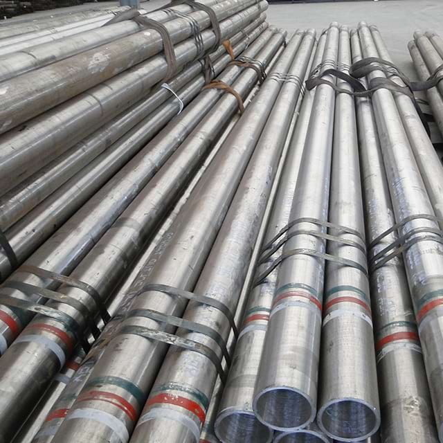 Seamless boiler tubes strap-bundled with painted ID bands for grade and heat traceability — segregated marking that prevents the grade mix-ups behind many replacement-tube failures.
What we have seen on replacement orders: On a coal-fired power plant in Southeast Asia, a failed T91 superheater tube was identified as long-term overheating failure after an emergency outage. The plant team replaced the tube and returned to service. Eighteen months later, the same failure mode recurred in the same location. Metallographic analysis of the second failed tube identified the replacement material as ASTM A213 Grade T22, not T91. The OD and wall were identical; the T22 tube had been supplied by the stores department from a batch labelled only by dimension, not by grade. T22 at 610°C has approximately 40% of T91's creep strength. The replacement tube had been creep-damaged from the first day of service. PMI (positive material identification) using an X-ray fluorescence analyser takes 30 seconds per tube and eliminates this failure mode entirely.
The Eight Failure Modes at a Glance
Boiler tube failures fall into eight recurring mechanisms. Use this table to narrow the diagnosis from the failure appearance before the detail below; the wrong diagnosis means the repair re-fails.
| # | Failure mode | Primary driver |
|---|---|---|
| 1 | Short-term overheating (stress rupture) | Rapid wall-temperature excursion 100–200 °C above design — thick-lip "fish-mouth" burst |
| 2 | Long-term overheating (creep) | Sustained 20–50 °C over design temperature accumulating creep damage |
| 3 | Waterside corrosion & pitting | Dissolved oxygen / poor water chemistry pitting the internal surface |
| 4 | Hydrogen damage | Atomic hydrogen from acidic waterside corrosion decarburising the steel |
| 5 | Fireside corrosion | SO₃ / molten-salt deposits attacking the external surface |
| 6 | Flyash erosion | Abrasive flyash particles thinning the wall at high-velocity zones |
| 7 | Corrosion fatigue | Cyclic thermal/mechanical stress + corrosion cracking |
| 8 | SCC (austenitic tubes) | Chloride/caustic + tensile stress cracking stainless/nickel-alloy tubes |
The most common single cause is overheating (modes 1–2), and the most common procurement-driven cause is a grade mix-up — as in the T91-vs-T22 case above. Material selection sits underneath most of these: see the ASTM A213 T11/T22/T91 alloy boiler tube guide → and the A192/A210 carbon-steel boiler tube specs →.
Why Failure Analysis Matters Before Replacement
Replacing a failed tube with the same material, in the same location, without addressing the root cause typically results in re-failure within one to three operating cycles. Root cause analysis requires three inputs: the fracture appearance (macroscopic), the microstructure (metallographic cross-section), and the operating history (temperature, pressure, water chemistry, load profile). This guide provides the macroscopic signatures for each mechanism — the first filter before sending samples to a metallurgical laboratory.
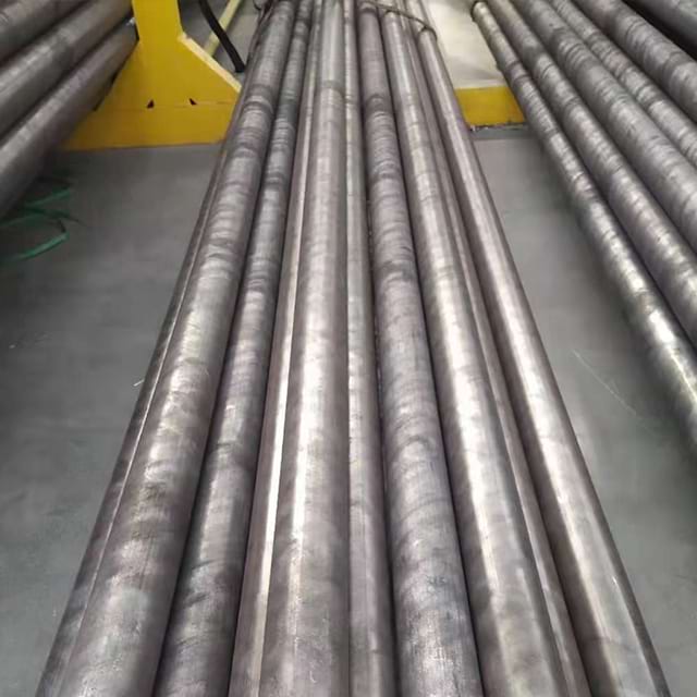 Seamless boiler tube stock viewed end-on down its length — the straight, defect-free bore that in-service failure mechanisms progressively degrade.
Failure Mode 1 — Short-Term Overheating (Stress Rupture)
What it is: Rapid tube wall temperature excursion above the material's short-term rupture limit — typically 100–200°C above the design temperature — causing ductile rupture within hours.
Appearance: Thick-lipped fish-mouth rupture at the hot-face (fireside) surface. The tube wall on the opposite side is undamaged. Significant bulging or blistering of the tube OD adjacent to the rupture. Metal appears dark and oxidised locally.
Root causes: Flow blockage (scale plug, weld debris, foreign object), partial blockage from internal oxide buildup reducing effective flow area, sudden loss of feedwater flow or a dry-out event, severe flame impingement.
Prevention: Regular boroscopic inspection of high-heat flux zones, chemical cleaning schedules to prevent oxide buildup, flow-monitoring instrumentation on critical circuits, flame scanner calibration to prevent impingement.
Short-term overheating and long-term overheating produce opposite fracture appearances and require opposite interventions. Short-term overheating (thick-lipped fish-mouth, ductile rupture) is prevented by maintaining adequate coolant flow — clearing blockages, monitoring flow velocity, preventing scale accumulation. Long-term overheating (thin-lipped fish-mouth, creep voids, no bulging) is prevented by controlling tube metal temperature — oxide scale management, spray calibration, load limit compliance. Diagnosing short-term overheating in a long-term overheating failure leads to the wrong intervention: the blockage-clearing programme finds nothing, and the new tube fails by creep within the same operating cycle.
Failure Mode 2 — Long-Term Overheating (Creep)
What it is: Progressive creep damage from sustained tube wall temperature 20–50°C above the material's design operating temperature, accumulating over months to years.
Appearance: Thin-lipped fish-mouth rupture or longitudinal cracking with little tube swelling. Microstructure shows creep voids at grain boundaries (requires metallography), carbide spheroidisation or coarsening, and intergranular cracking near the fracture. The tube OD on the hot face may be slightly enlarged.
Root causes: Gradual oxide scale buildup on the waterside increasing thermal resistance and raising metal temperature; load increases above original design; degraded spray cooling in superheater circuits; tube misalignment affecting gas flow distribution.
Prevention: Periodic tube replacement schedules for high-temperature superheater and reheater circuits based on creep life calculations, metallographic replica sampling during major overhauls to assess creep void density, oxide exfoliation monitoring to detect scale accumulation.
Failure Mode 3 — Waterside Corrosion and Pitting
What it is: Electrochemical dissolution of the tube waterside surface, producing pits, general wall thinning, or a combination, driven by dissolved oxygen, acidic pH, or under-deposit concentration of corrosives.
Appearance: Hemispherical or elongated pits on the internal surface, typically on the bottom of horizontal tubes (oxygen pitting) or on the heat-flux face (under-deposit). Pits often contain dark oxide or magnetite deposits. Wall thinning may not be visible externally until the tube is cut for inspection.
Root causes: Inadequate oxygen scavenging in feedwater treatment (dissolved oxygen attack during shutdown or start-up); acidic condensate return from leaking heat exchangers; under-deposit acid concentration at heavy oxide scale.
Prevention: Maintain feedwater dissolved oxygen below 7 μg/kg; use deaerators with proper venting; add chemical oxygen scavengers (hydrazine or DEHA) appropriate for operating pressure; verify condensate quality continuously; blowdown schedules to prevent deposit accumulation.
Failure Mode 4 — Hydrogen Damage
What it is: Subsurface decarburisation and grain boundary cracking caused by atomic hydrogen generated by acidic waterside corrosion reacting with iron carbides to form methane.
Appearance: The tube may rupture suddenly with a brittle, 'window-pane' or 'alligator-hide' fracture surface. There is little external deformation. The tube wall cross-section shows a decarburised zone (white layer) on the waterside surface visible under low-magnification microscopy. Advanced cases show extensive intergranular fissuring.
Root causes: Severe acidic excursion in boiler water (pH below 7, typically due to condenser tube leak of cooling water), sustained acid attack at under-deposit sites where acid concentrates by evaporation.
Prevention: Continuous boiler water conductivity and pH monitoring with automatic alarm and shutdown; condenser leak detection; immediate investigation of any pH reading below 8.0; acid-phosphate corrosion prevention through coordinated phosphate treatment.
Critical note: Hydrogen damage is irreversible. Once identified, all tubes in the affected zone should be replaced. A tube with hydrogen damage has unpredictably reduced fracture toughness and should not remain in service regardless of remaining wall thickness.
Failure Mode 5 — Fireside Corrosion
What it is: Chemical attack on the tube external surface by combustion products, particularly sulfur trioxide (SO₃) forming sulfate deposits on metal surfaces below the acid dew point, and vanadium pentoxide (V₂O₅) from fuel oil ash acting as a flux to dissolve the protective oxide.
Appearance: Irregular external surface pitting and grooving on the gas-side face, covered by hard, dense deposits (sulfates, vanadates). The tube wall shows an orange-to-black corrosion product layer. In severe cases, through-wall pits develop from outside. Most common in oil-fired or waste-fuel boilers.
Root causes: Metal surface temperature in the range 565–700°C where liquid sulfate-vanadate deposits are most aggressive; high vanadium and sulfur content in the fuel; inadequate sootblowing allowing deposit accumulation.
Prevention: Fuel additives (magnesia, MgO) to raise the melting point of vanadate deposits; adjust tube metal temperature away from the aggressive range through spray cooling or flow redistribution; increase sootblowing frequency; switch to lower-sulfur / lower-vanadium fuel blends.
Failure Mode 6 — Flyash Erosion
What it is: Progressive wall thinning by abrasion from flyash particles entrained in the flue gas stream, concentrated at high-velocity impingement zones in the convection pass, economiser, and at tube bends.
Appearance: Smooth, uniform wall thinning on the downstream side of the tube (the side facing the approaching gas flow). The eroded surface is shiny and metallic, free of corrosion products. Tubes at the leading edge of convection tube banks and at tube bends in the economiser are preferentially affected. No cracking.
Root causes: High flue gas velocity through the convection pass; high-silica, high-abrasive-index coal; tubes positioned at gas lane edges where flow is locally accelerated; disturbed flow from sootblower erosion upstream.
Prevention: Periodic UT thickness mapping of erosion-prone zones; sacrificial erosion shields or thermal spray coatings on critical tubes; combustion tuning to reduce ash loading; seal welding of tube-to-baffle clearances to eliminate gas bypassing.
Failure Mode 7 — Corrosion Fatigue
What it is: Fatigue cracking initiated by cyclic thermal or mechanical stress and accelerated by corrosion, producing crack growth at stress levels well below those that would cause purely mechanical fatigue.
Appearance: Multiple parallel transverse cracks on the waterside surface, often initiating from pits or at oxide notches. Cracks are transgranular, tightly wedge-shaped, and may be filled with oxide. Common locations: tube-to-header welds, tube stub attachments, and waterwall tubes near sootblower impingement zones. Associated with frequent start-stop cycling.
Root causes: Repeated thermal cycling (particularly in peaking or cycling-duty boilers); stress concentration at welds or attachments; corrosive water chemistry initiating pits that act as crack starters; waterwall tubes subject to repeated thermal shock from sootblower steam.
Prevention: Reduce start-stop cycling rate where possible; redesign tube-to-header connections to reduce stress concentration; maintain water chemistry within specification to prevent pitting; use high-cycle fatigue screening criteria (not just static stress analysis) for tube attachment designs.
Failure Mode 8 — Stress Corrosion Cracking (SCC) in Austenitic Tubes
What it is: Brittle cracking of austenitic stainless steel or nickel-alloy superheater and heat exchanger tubes driven by the simultaneous presence of tensile stress, a specific corrosive environment (typically chloride or caustic), and elevated temperature.
Appearance: Multiple branching cracks, transgranular (in chloride SCC) or intergranular (in caustic SCC), initiating from the external or internal surface. No ductile deformation. Most common in 304/316 stainless steel grade boiler tubes in service environments with chloride contamination or caustic carryover from drum boilers.
Root causes: Contamination of feedwater or steam by chlorides (condenser leakage, saltwater intrusion); caustic concentration at under-deposit sites; welding residual stress in as-welded tubing without post-weld stress relief; tube OD temperature in the sensitisation range (550–850°C) for Type 304 tubes.
Prevention: Specify stabilised grades (ASTM A213 TP321 or TP347) or low-carbon grades (TP304L, TP316L) to reduce sensitisation susceptibility; post-weld heat treatment or solution annealing of tube welds; eliminate chloride sources from feedwater; apply solution annealing to austenitic tubes after any field welding repairs.
Critical Procurement-Phase Failure Modes
The eight failure modes above are operational in origin — they develop during service from temperature, chemistry, or mechanical loading conditions. The three failure modes below originate in procurement and installation decisions made before the tube ever sees steam pressure. They are less frequently discussed and more frequently misdiagnosed, because the failed tube looks like a service failure when the root cause is in the purchase order or the stores bin.
Failure Mode — Wrong Replacement Material Installed
Mechanism: T91 (9Cr-1Mo-V-Nb) superheater tube replaced with T22 (2.25Cr-1Mo) because both had the same OD and wall in stock and the grade label on the stores bin was ambiguous. T22 at 610°C has creep strength approximately 40% of T91. The replacement tube creeps and deforms from the first operating cycle, producing a failure that mimics long-term overheating in appearance but occurs within 12–18 months rather than years.
Diagnostic: PMI using an X-ray fluorescence (XRF) analyser on the failed tube identifies 2.25% Cr, 1.0% Mo, absence of V and Nb — T22, not T91. Metallographic cross-section shows creep void density inconsistent with the short service duration, confirming early-stage creep failure from under-strength material.
Fix: Require PMI on every replacement boiler tube using XRF or OES before installation — 30 seconds per tube. Store boiler tube grades in segregated bays with permanent marking on each tube, not only on the bundle. Never accept a tube from general stores without grade verification against the original engineering drawing.
Failure Mode — T91 or T22 Weld Repair Without PWHT
Mechanism: A hairline crack or pinhole weld defect in a T22 or T91 tube is repaired by GTAW without post-weld heat treatment (PWHT) to save outage hours. The weld HAZ in Cr-Mo steel is hardened by the weld thermal cycle; hydrogen diffusing from the weld process is trapped in the hard HAZ. Within 2,000–5,000 operating hours, hydrogen-assisted cracking initiates in the HAZ. The repair weld itself is intact; the failure is in the parent metal immediately adjacent to it.
Diagnostic: Failure at the toe of the repair weld rather than within the original defect zone. Metallographic cross-section shows intergranular cracking with no evidence of original defect at the failure initiation site. HAZ hardness above 350 HB — well above the 200 HB safe limit for hydrogen cracking resistance.
Fix: PWHT is mandatory for all Cr-Mo alloy steel welds (T11, T22, T91) per ASME Section I and most national boiler codes, regardless of wall thickness. Specify PWHT requirements on the repair WPS before any weld repair begins. Accept the outage extension for PWHT; the cost of the second unplanned outage is 3–5× higher than the original PWHT delay.
Failure Mode — Oversize Replacement Tube Installed
Mechanism: Original tube OD is 50.8 mm. Replacement tube sourced as "51mm OD" from local stock — a slightly larger OD from a metric standard batch. The tube fits the header bore with slight interference. During thermal expansion at operating temperature, the interference-fit tube cannot expand freely; the header collar acts as a stress concentration. Thermal fatigue cracking initiates at the tube-to-header joint within 3–6 months.
Diagnostic: Failure at the tube-to-header junction rather than in the tube body. Crack pattern is circumferential (thermal fatigue signature) rather than longitudinal (creep or pressure signature). Dimensional measurement of the failed tube confirms OD oversize.
Fix: Specify replacement tube OD tolerance on the PO: OD to the original engineering drawing with ASTM A192/A210/A213 dimensional tolerance applied. Verify OD with a micrometer at goods receipt before installation. For critical superheater tubes, require the tube to gauge the header bore before installation is approved.
Failure Pattern Analysis — Systematic vs Isolated Failure
When evaluating a boiler tube failure, the pattern is as informative as the mechanism:
| Pattern | Probable cause | Action |
|---|---|---|
| Single isolated failure, no history | Blockage or mechanical damage | Repair and monitor |
| Multiple failures in same circuit, same location | Systematic flow, chemistry, or temperature issue | Root cause investigation before repair |
| Failures moving progressively along tube banks | Advancing erosion or creep life consumption | Systematic panel replacement |
| Failures concentrated at welds or attachments | Fatigue, SCC, or weld quality | Redesign attachment detail; inspect all similar welds |
| Same failure repeating within 1–2 years of repair | Wrong root cause diagnosis | Send tube samples for metallographic analysis |
A single replacement without addressing the pattern is the leading cause of repeat failures and extended unplanned outages. The cost of a proper metallurgical failure analysis — typically a few thousand dollars — is trivial against the cost of a second unplanned shutdown within the same year.
Remaining Wall Life from UT Monitoring Data
Before scheduling tube replacement, quantify remaining life from UT data rather than replacing on a fixed calendar cycle. For a 50.8 mm OD waterwall tube (ASTM A210 Grade A-1) at 21 MPa operating pressure, the calculation proceeds in two steps.
Step 1 — Calculate ASME B31.1 minimum wall thickness:
Allowable stress S at 400°C from ASME Section II for A210 Grade A-1: S = 103 MPa. Using the thin-wall formula where E = 1.0 (seamless):
t_min = P × D / (2 × S × E + 0.8 × P) t_min = 21 × 50.8 / (2 × 103 × 1.0 + 0.8 × 21) t_min = 1066.8 / (206 + 16.8) t_min = 1066.8 / 222.8 = 4.79 mm
Step 2 — Calculate remaining life from UT reading:
Original nominal wall: 6.3 mm. Minimum manufactured wall applying 12.5% undertolerance: 6.3 × 0.875 = 5.51 mm. Current UT reading: 5.2 mm. Design minimum per ASME B31.1: 4.79 mm.
Available corrosion allowance from current reading: 5.2 − 4.79 = 0.41 mm remaining to ASME minimum.
Measured erosion/corrosion rate from last two UT surveys (18 months apart): 0.5 mm / 18 months = 0.33 mm/year.
Remaining life = 0.41 mm / 0.33 mm/year = 1.24 years ≈ 15 months before the tube reaches ASME minimum wall.
Decision: Schedule replacement in the next planned outage within 12 months. Immediate action: increase UT monitoring frequency to 6-month intervals for this tube and the adjacent tubes in the same panel. A tube at 5.2 mm wall has no margin for an accelerated corrosion event during the remainder of the operating cycle.
This calculation is the correct basis for replacement scheduling. Replacing at a fixed calendar interval without UT data either replaces tubes that have years of remaining life or — more dangerously — allows tubes that are corroding faster than assumed to remain in service past their ASME minimum.
When NOT to Repair Without Root Cause Investigation
Weld repair is an appropriate response to isolated mechanical damage with no systemic cause. For every other failure scenario, repair without root cause investigation produces a second failure. The table below defines the decision boundary.
| Failure pattern | Correct action | Wrong action |
|---|---|---|
| Single isolated failure, first occurrence | Weld repair if remaining wall is above ASME minimum | No investigation needed |
| Same tube or same location fails twice | Full metallographic root cause analysis before any further repair | Second weld repair |
| Multiple failures in same circuit panel | Replace panel and investigate root cause (flow, chemistry, temperature) | Replace only the failed tubes |
| Failures confirmed as hydrogen damage | Replace all affected-zone tubes; correct water chemistry immediately | Tube repair — hydrogen damage is irreversible |
| Failure after recent repair without PWHT | Metallographic check for HAZ hydrogen cracking; PWHT the repair | Assume previous repair failed mechanically |
| Pattern moves progressively along tube bank | Systematic panel replacement scheduled by creep life calculation | Spot-replace as each failure occurs |
The pattern "same location fails twice" is a hard stop. A second weld repair at the same location, without metallographic analysis of the first failed tube, is not a maintenance decision — it is a scheduled unplanned outage deferred by six to eighteen months.
Purchase Order Guidance — Replacement Tube Procurement
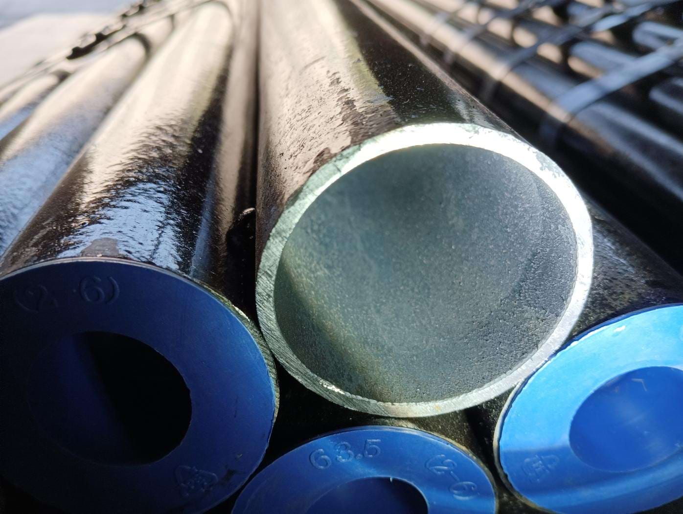 Tube ends with a bare bore and blue end caps stamped with the size — verifying OD, wall, and grade marking at goods receipt is the procurement step that prevents wrong-material and oversize-tube failures.
When ordering replacement boiler tubes, the dimensional match is only the starting point. Grade, heat treatment, documentation, and PMI requirements all appear on the PO, not in the stores bin.
Wrong PO: "ASTM A213 T91 seamless boiler tube, OD 50.8 mm, wall 6.3 mm."
What ships: The mill supplies T91 tube with correct dimensions and chemistry, but the MTC does not show the tempering temperature. The tube was tempered at 700°C instead of the 730°C minimum per ASTM A213. Hardness is 240 HB — within the 250 HB limit. Tensile properties pass. The MTC looks complete to a dimensional checker. The tube enters service with sub-optimal creep resistance and no way to detect the deficiency without destructive testing.
Correct PO additions for T91:
- Specification and grade: ASTM A213 Grade T11, T22, or T91 for alloy steel; ASTM A192 or A210 Grade A-1 for carbon steel waterwall tubes
- Manufacturing process: seamless (standard for all pressure service)
- OD and wall thickness: confirm from the original engineering drawing, not from a failed tube (which may be swollen)
- Heat treatment: normalised and tempered for T91; as-rolled or normalised for carbon grades; tempering temperature ≥ 730°C documented on MTC
- Al ≤ 0.02% verified separately — excess aluminium destroys creep resistance by blocking nitrogen from stabilising carbides
- PMI mandatory at goods receipt using XRF to confirm 9Cr-1Mo chemistry, separate from chemistry listed on the MTC
- Grade marked on each individual pipe joint, not only on the bundle label
- NDE: hydrostatic test per standard; specify UT or eddy current if the failure was associated with a weld defect
- Mill documentation: EN 10204 Type 3.1 MTC with full chemical, mechanical, and hardness results; tempering temperature as a separate line item
The Al ≤ 0.02% limit for T91 is the most frequently overlooked specification point. ASTM A213 does not set a maximum aluminium limit in its grade table; it appears in a supplementary requirement. Mills that do not understand the requirement ship tube that passes all standard acceptance criteria and fails by creep ahead of schedule. Ask for the Al result on the MTC explicitly — most compliant mills will have it.
For full grade specifications and mechanical property tables, see the ASME boiler tube specification tables →
Use the Unit Converter → to verify OD, wall, and length dimensions across imperial and metric systems.
Frequently Asked Questions
What is the most common cause of boiler tube failure?
Short-term overheating — also called short-term overheat rupture — is statistically the most reported single failure mechanism in utility and industrial boilers. It occurs when a tube experiences a rapid temperature excursion above the material's design limit, typically caused by a flow blockage, scale accumulation, or a sudden load swing. The tube wall bulges and ruptures within hours or days, producing a thick-lipped, fish-mouth opening on the hot-side surface.
How do you identify a long-term overheating failure in a boiler tube?
Long-term overheating produces a thin-lipped, fish-mouth rupture or a longitudinal split with minimal tube swelling, combined with visible creep void formation in the tube wall microstructure. The fracture surface shows intergranular cracking and carbide precipitation at grain boundaries — a microstructural signature of prolonged exposure above the material's creep limit. The failure location is typically on the hot-gas side of the tube, and surrounding tubes often show spheroidisation of carbides indicating extended high-temperature exposure.
What causes corrosion fatigue in boiler tubes?
Corrosion fatigue arises when cyclic thermal stress and corrosive attack combine to initiate and propagate cracks that neither mechanism would cause independently. In boilers, it typically occurs at tube attachment welds, near sootblower impingement zones, and at waterwall tube-to-header connections subject to repeated on-off cycling. The cracks are transgranular, initiate from pits or oxide notches on the water-side surface, and propagate perpendicular to the applied stress. Reducing start-stop frequency, improving water chemistry control to suppress pitting, and redesigning attachment welds to reduce stress concentration are the main preventive measures.
What is hydrogen damage in boiler tubes?
Hydrogen damage (also called hydrogen embrittlement or hydrogen attack in boilers) occurs when hydrogen generated by waterside corrosion — typically acidic attack at low pH — diffuses into the steel and reacts with iron carbides to form methane gas at grain boundaries. The methane cannot diffuse out and accumulates as voids and cracks, decarburising the steel and causing it to lose both tensile strength and ductility. The damaged zone often appears as a 'window-pane' fracture or a sudden brittle failure with little external deformation. Hydrogen damage is irreversible — affected tubes must be replaced, and boiler water chemistry must be corrected immediately.
How can erosion by flyash be prevented in boiler tubes?
Flyash erosion prevention requires a combination of operational and design measures. Coal quality control — avoiding high-silica, high-ash coals — reduces the abrasive particle load. Reducing flue gas velocity in the erosion-prone zones (convection pass, economiser, and air heater entry) below the erosion threshold for the tube material is the primary engineering control. Shield tiles, sacrificial cladding strips, and erosion-resistant thermal spray coatings (typically WC-Co or Cr3C2-based) protect high-wear tubes. Periodic thickness monitoring by ultrasonic testing identifies the onset of erosion before it reaches the alarm threshold.
What water chemistry parameters are most important for preventing waterside corrosion in boiler tubes?
The three most critical parameters for waterside corrosion control are pH, dissolved oxygen, and silica concentration. For drum boilers operating below 60 bar, ASME consensus guidelines recommend feedwater pH 8.8–9.2 (phosphate treatment) or 9.0–9.6 (AVT — all-volatile treatment), dissolved oxygen below 7 μg/kg, and boiler water silica below the pressure-dependent carryover limit. Deviations from pH — particularly acidic excursions below pH 7 — cause hydrogen damage and acid pitting. High silica causes deposits that impair heat transfer and initiate under-deposit corrosion. Regular blowdown, condensate polishing, and continuous conductivity monitoring are essential.
What nondestructive examination (NDE) methods are used to assess boiler tube condition?
The main NDE methods for in-service boiler tube inspection are ultrasonic thickness measurement (UTM) for waterwall and screen tube erosion/corrosion monitoring, eddy current testing (ECT) for heat exchanger tube defect detection, phased array ultrasonic testing (PAUT) for weld integrity assessment, and metallographic replication (field replica) for creep assessment in high-alloy tubes such as T91. For furnace waterwall tubes in coal-fired boilers, scanning UTM using semi-automated crawler systems provides full-coverage thickness maps. Hydrogen damage assessment requires destructive metallography on tube samples; NDE alone cannot reliably detect advanced hydrogen attack.
When should a boiler tube be replaced rather than repaired?
A tube should be replaced — not repaired — when the remaining wall thickness is below the code-minimum calculated thickness at any point, when hydrogen damage is confirmed in the microstructure (even if the tube has not yet failed), when creep life consumption exceeds about 80% based on replica metallography or life assessment, or when the failure history in a tube panel shows a pattern indicative of systematic damage (e.g., multiple acid attack failures in one zone). Sleeve repairs and plug-in patches are acceptable for isolated mechanical damage but are not appropriate for systemic damage mechanisms. A repaired tube in a damaged panel is likely to be followed by adjacent failures.