
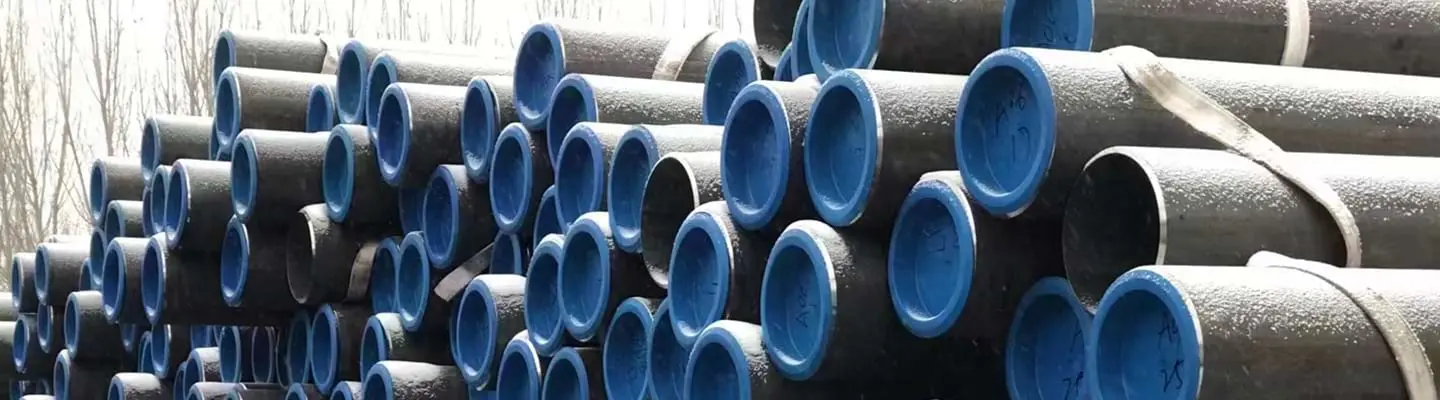
ASME B36.10M is the dimensional foundation of carbon and alloy steel pipe engineering. Every OD, wall thickness, and weight table that an engineer, procurement team, or mill refers to when specifying pipe traces back to this standard. Yet the schedule system is consistently misunderstood — engineers assume schedule numbers scale linearly, that STD equals Sch 40 at all sizes, or that a higher schedule means a proportionally heavier pipe regardless of NPS. These assumptions cause specification errors that range from undersized walls for design pressure to unnecessary cost from over-specified schedules.
ZC Steel Pipe supplies seamless and welded line pipe in all standard ASME B36.10M dimensions from NPS ½ to NPS 60, across Sch 10 through XXS, in API 5L grades from Grade B to X80 PSL2. We supply to pipeline contractors, refineries, and EPC teams across Africa, the Middle East, South America, and Southeast Asia. This guide explains how the schedule system works, how to select the right schedule for a design pressure, and how to read the B36.10M table correctly.
Quick Answer
A pipe schedule is a nominal wall designation, not a fixed thickness — Sch 40 is 3.91 mm on NPS 2 but 10.31 mm on NPS 12. STD and XS diverge from the numbered schedules on large pipe, which is where most specification errors begin:
| Designation | NPS ⅛–10 | NPS 12 and larger |
|---|---|---|
| STD | Equals Sch 40 (wall varies by size) | Constant 9.53 mm (0.375 in) |
| XS | Equals Sch 80 (through NPS 8) | Constant 12.70 mm (0.500 in), NPS 8 and up |
| Sch 40 / Sch 80 | Wall increases with size | Wall keeps increasing with size |
For NPS 14 and above, always state the nominal wall in millimetres on the purchase order — a schedule name alone is not a complete wall specification. To size a schedule from a design pressure, work the four-step Barlow method below or run the pipeline design calculator.
What we see on large-diameter orders: On an FPSO topsides project in West Africa, a piping engineer specified NPS 20 STD for a seawater cooling header. The reasoning: NPS 6 STD = Sch 40 = 7.11 mm, which is the "standard heavy wall" for that size. By the same logic, NPS 20 STD was interpreted as "the standard heavy wall for NPS 20." What shipped was NPS 20 × 9.53 mm wall — the constant STD definition for NPS ≥ 14 per ASME B36.10M. The design pressure calculation required a minimum wall of 14.3 mm. The pipe was delivered with correct markings (NPS 20 STD per ASME B36.10M — fully compliant to the order as written), installed, and found deficient during the pressure test at 85% of rated test pressure. Eleven pipe joints and associated spools were scrapped and replaced — an 8-week schedule impact. For NPS 14 and above, specifying "STD" or "XS" is not a complete wall specification — the nominal wall in millimetres must always be stated alongside.
What ASME B36.10M Is — and Is Not
ASME B36.10M, Welded and Seamless Wrought Steel Pipe — Dimensions and Weights, published by the American Society of Mechanical Engineers, defines the standardized dimensions for carbon and alloy steel pipe: outside diameter, wall thickness, inside diameter, and plain-end weight per unit length. The current edition is 2018 (verified to be identical to the 2022 reaffirmation in all dimensional content).
B36.10M specifies: OD, wall thickness, ID, and weight. Nothing else.
B36.10M does not specify: Material grade, chemical composition, mechanical properties, manufacturing method (seamless vs. welded), pressure rating, or corrosion resistance. These are governed by material product standards (API 5L, ASTM A53, ASTM A106, ASTM A335) and design codes (ASME B31.3, ASME B31.8, ASME B31.4).
This distinction matters for procurement. Ordering "Sch 40 pipe" without a material specification is not a complete pipe order. A complete specification requires both a material standard (which governs what the pipe is made of and how it performs) and a dimensional reference (which governs what sizes and walls are supplied). For line pipe, that material standard is API 5L, where the PSL1 vs PSL2 choice sets the testing, chemistry, and toughness — none of which B36.10M touches.
The Pipe Size Naming Convention — NPS and DN
ASME B36.10M uses NPS (Nominal Pipe Size) as the primary size identifier. NPS is a nominal designation — for NPS 14 and larger, the NPS number equals the OD in inches. For NPS 12 and smaller, the NPS number does not equal the OD.
| NPS | OD (inches) | OD (mm) | Notes |
|---|---|---|---|
| ½ | 0.840 | 21.3 | OD ≠ NPS |
| 2 | 2.375 | 60.3 | OD ≠ NPS |
| 4 | 4.500 | 114.3 | OD ≠ NPS |
| 8 | 8.625 | 219.1 | OD ≠ NPS |
| 12 | 12.750 | 323.9 | OD ≠ NPS |
| 14 | 14.000 | 355.6 | OD = NPS (inches) |
| 24 | 24.000 | 609.6 | OD = NPS (inches) |
The NPS/OD relationship changes at NPS 14. Below NPS 14, the OD is larger than the nominal size — a convention inherited from wrought iron pipe trade sizes. At NPS 14 and above, the OD in inches equals the nominal pipe size exactly. DN (Diameter Nominal, the SI equivalent) is the metric designation: DN 100 corresponds to NPS 4, DN 300 to NPS 12, DN 600 to NPS 24. The DN designation is used in ISO and European standards; NPS in American standards. Both appear on pipe markings and procurement documents.
Schedule Designations
ASME B36.10M defines the following schedule designations for carbon and alloy steel pipe:
| Schedule | Description |
|---|---|
| Sch 5 | Thin wall, low pressure — limited to certain NPS ranges |
| Sch 10 | Light wall — generally available NPS ½ and larger |
| Sch 20 | Moderate wall |
| Sch 30 | Moderate wall |
| Sch 40 | Standard for most applications ≤ NPS 10 |
| Sch 60 | Medium-heavy wall |
| Sch 80 | Heavy wall |
| Sch 100 | Heavy wall — limited NPS availability |
| Sch 120 | Extra heavy |
| Sch 140 | Extra heavy |
| Sch 160 | Heaviest standardized schedule |
| STD | Standard wall — equals Sch 40 for NPS ⅛–10; then constant 9.53 mm for NPS 14+ |
| XS | Extra Strong — equals Sch 80 for NPS ⅛–8; then constant 12.70 mm for NPS 8+ |
| XXS | Double Extra Strong — heavier than Sch 160 for NPS ≤ 6 |
Not all schedules are available at every NPS. Sch 5 is limited to larger NPS sizes where it provides a meaningful thin-wall option. Sch 160 and XXS are available only through NPS 12 or NPS 6 respectively in most size ranges. A procurement team specifying Sch 160 on NPS 20 will find the schedule does not exist in B36.10M — the order will require a nominal wall specification instead.
The STD and XS Divergence — The Most Common Misconception
The schedule designations STD (Standard) and XS (Extra Strong) are frequently misunderstood to be synonymous with Sch 40 and Sch 80 across all sizes. This is only true for smaller pipe:
For NPS ⅛ through NPS 10: STD = Sch 40. The wall thicknesses are identical. For NPS 12 and larger: STD is defined as a constant 9.53 mm (0.375 in) wall, while Sch 40 continues to increase with pipe size. An NPS 24 pipe in STD has a 9.53 mm wall; NPS 24 Sch 40 (where it exists in the table) would be thicker.
For NPS ⅛ through NPS 8: XS = Sch 80. The wall thicknesses are identical. For NPS 8 and larger: XS is defined as a constant 12.70 mm (0.500 in) wall, while Sch 80 continues to increase. An NPS 16 pipe in XS has a 12.70 mm wall; NPS 16 Sch 80 is thicker.
The practical implication: for large-diameter pipe (NPS 14 and above), the STD designation means a specific constant wall, not "standard for that size." Specifying NPS 20 STD gives 9.53 mm wall regardless of the application pressure. This is often lighter than what the design pressure requires — confirm the wall thickness number, not just the schedule identifier, when specifying large-diameter pipe.
API 5L permits a wall thickness mill tolerance of −12.5% for seamless pipe and −8% for LSAW/SAWL pipe. This means a pipe ordered to 12.7 mm nominal wall may be delivered with a measured wall as low as 12.7 × 0.875 = 11.11 mm (seamless) — and the pipe fully meets the API 5L dimensional standard. If the Barlow design calculation requires a minimum wall of exactly 12.7 mm, the order fails at the lower tolerance. The correct approach is to calculate the "ordering wall" (t_order) as t_min / (1 − tolerance factor): for API 5L seamless, t_order = t_min / 0.875. This ordering wall is always higher than the design minimum wall, and ensures that even at the lower API 5L tolerance, the delivered pipe meets the pressure requirement. When the calculated t_order falls between standard schedule walls, select the next thicker schedule.
How to Select a Schedule for Design Pressure
Schedule selection is a structured four-step process. The two-step shortcut — calculate t_min, then pick a schedule — is incorrect because it ignores mill tolerance and produces an order where a portion of the delivered pipe may be at or below the design minimum wall.
Step 1: Calculate the minimum required wall thickness
Use the Barlow formula from the applicable design code:
t_min = P × D / (2 × SMYS × F × E × T)
Where:
- P = design pressure
- D = outside diameter (from B36.10M for the chosen NPS)
- SMYS = specified minimum yield strength of the pipe material (from API 5L, ASTM A106, etc.)
- E = longitudinal joint factor (1.0 for seamless; 0.80 for ERW per ASME B31.3; varies by code)
- F = design factor per applicable code (0.72 for gas pipelines per ASME B31.8 in Class 1; varies)
- T = temperature derating factor (1.0 for T < 120°C per ASME B31.8)
Step 2: Apply mill tolerance to get the ordering wall
For API 5L seamless pipe (−12.5% tolerance): t_order = t_min / 0.875
For API 5L LSAW/SAWL pipe (−8% tolerance): t_order = t_min / 0.920
This step is mandatory. Ordering at t_min rather than t_order means some joints in the delivery will be below the design minimum wall, have correct pipe markings, and pass all API 5L acceptance criteria. The tolerance you apply depends on manufacturing route, so confirm seamless vs welded before fixing the ordering wall.
Step 3: Add corrosion allowance
t_spec = t_order + CA, where CA is the corrosion allowance from the project specification. For sour or wet gas service, CA is typically 1.0–3.0 mm depending on the fluid and the design life.
Step 4: Select the schedule
From the ASME B36.10M table for the chosen NPS, find the lowest schedule whose nominal wall thickness is ≥ t_spec. That is the pressure-minimum schedule. If the project specification sets a minimum schedule for this NPS regardless of pressure (common in sour service or offshore project specifications), apply that minimum instead if it results in a heavier wall.
Schedule Selection Worked Example
Full four-step Barlow schedule selection for a real design condition:
Conditions: NPS 8 (OD = 219.1 mm per ASME B36.10M), API 5L X65 PSL2 seamless, ASME B31.8 Class 1 Location.
| Parameter | Value |
|---|---|
| Design pressure P | 10 MPa |
| SMYS (X65) | 448 MPa |
| Design factor F (Class 1 Location, ASME B31.8) | 0.72 |
| Longitudinal joint factor E (seamless) | 1.0 |
| Temperature derating factor T (T < 120°C) | 1.0 |
| Corrosion allowance CA (sour/wet gas) | 1.5 mm |
Step 1 — Barlow minimum wall:
t_min = P × D / (2 × SMYS × F × E × T) = 10 × 219.1 / (2 × 448 × 0.72 × 1.0 × 1.0) = 2191 / 645.1 = 3.40 mm
Step 2 — Ordering wall (API 5L seamless, −12.5% tolerance):
t_order = t_min / (1 − 0.125) = 3.40 / 0.875 = 3.89 mm
Step 3 — Add corrosion allowance:
t_spec = t_order + CA = 3.89 + 1.50 = 5.39 mm
Step 4 — Select from ASME B36.10M for NPS 8:
| Schedule | Nominal wall (mm) | Meets t_spec ≥ 5.39 mm? | Result |
|---|---|---|---|
| Sch 10 | 3.76 | No — 3.76 < 5.39 | INSUFFICIENT |
| Sch 20 | 5.56 | Yes — 5.56 ≥ 5.39 | MINIMUM ADEQUATE SCHEDULE |
| Sch 40 (STD) | 8.18 | Yes — adequate | Over-specified by 51% |
Selection: NPS 8 Sch 20, API 5L X65 PSL2 seamless.
Note: if the customer's project specification requires Sch 40 as a minimum for NPS 8 regardless of pressure requirements — common in sour service or offshore project specifications — Sch 40 is selected over the pressure-minimum Sch 20. The project specification minimum always overrides the pressure minimum when it results in a heavier wall.
The full ASME B36.10M dimensional table for all NPS and schedule combinations is available at the ZC Steel Pipe pipe schedule chart.
Schedules by Application Context
The following are common schedule selections by application type. These are starting points — always confirm against your design pressure calculation:
| Application | Typical NPS Range | Common Schedule |
|---|---|---|
| Low-pressure gathering line | 2–8 | Sch 20 or Sch 30 |
| Gas distribution (moderate pressure) | 2–12 | Sch 40 (STD) |
| Process pipe (refinery, chemical) | ½–12 | Sch 40 to Sch 80 depending on fluid |
| High-pressure process (hydrocracker, reformer) | ½–6 | Sch 80 to Sch 160 |
| Transmission pipeline (X65/X70) | 12–60 | Wall per B36.10M at calculated thickness; typically 10–19 mm |
| Subsea/offshore (X65 LSAW) | 16–56 | Wall per design — Sch 60 to custom-wall |
| Hydraulic/instrument tubing | ⅛–1 | Sch 80 or Sch 160 |
For large-diameter transmission pipe (NPS 16 and above), wall thicknesses are typically specified as nominal wall values (e.g., 14.3 mm or 17.5 mm) rather than schedule designations, because the walls required by ASME B31.8 design pressures for X65/X70/X80 do not always align with standard schedules. The ASME B36.10M table is used to confirm that the specified wall and OD produce a valid pipe geometry, and the mill rolls to the specified wall. This is different from process plant pipe, where schedule designations are used throughout the piping specification and every size is drawn from the B36.10M table directly.
For how those large-diameter walls are actually manufactured, see the welded steel pipe types guide (ERW, LSAW, SSAW) and LSAW vs seamless for large-diameter pipelines — the manufacturing route you choose also sets the wall tolerance you must design around.
When NOT to Specify by Schedule Name for NPS ≥ 14
For smaller pipe (NPS 12 and below), schedule names are unambiguous — Sch 40 maps to a specific wall that varies by size, and engineers look it up. For NPS 14 and above, schedule names become misleading because STD and XS describe constant walls that do not scale with pipe size. The following table identifies the situations where a schedule designation is not a complete specification:
| Situation | Recommended specification method | Why schedule name fails |
|---|---|---|
| NPS 14 and above (all applications) | Specify nominal wall in mm + OD in mm per ASME B36.10M | STD = 9.53 mm constant; XS = 12.70 mm constant — schedule names describe a fixed wall unrelated to the pipe diameter |
| Transmission pipeline (ASME B31.8 design) | Specify nominal OD + nominal wall from Barlow calculation | Pipeline walls per design calculation rarely align exactly with standard schedule increments above NPS 14 |
| Offshore/subsea pipe | Always OD + wall in mm | Standard schedules not used above NPS 24 for offshore; all ordering by OD + wall |
| Wall thickness tolerance is critical | State t_order (not t_min) | Nominal wall includes tolerance band; ordering t_min gives pipe that meets standard but is below design requirement at lower tolerance |
| Large-bore fittings matching large-bore pipe | State wall at each end in mm | Fitting schedule designations have same STD/XS ambiguity as pipe above NPS 14 |
The piping specification for any project that includes NPS 14 and above pipe should include an explicit note: schedule designations (STD, XS) are not acceptable as the sole wall specification for large-diameter pipe. This prevents ambiguity throughout the supply chain from the PO through the mill MTC to the receiving inspection.
Weight Calculation
Plain-end weight in kg/m from the ASME B36.10M formula:
W = (OD_mm − WT_mm) × WT_mm × 0.0246615
The constant 0.0246615 = carbon steel density (7,850 kg/m³) × π/4 ÷ 10⁶.
This is the weight of the steel shell only. Bevelled-end or threaded-end pipe weighs slightly more due to end preparation. Pipe with internal coatings, external coatings, or concrete weight coating adds substantially to running weight — relevant for offshore pipeline installation load calculations. For an NPS 8 Sch 40 pipe (OD 219.1 mm, WT 8.18 mm): W = (219.1 − 8.18) × 8.18 × 0.0246615 = 210.92 × 8.18 × 0.0246615 = 42.55 kg/m. This confirms the weight increase from Sch 20 (5.56 mm wall, 28.27 kg/m) to Sch 40 (8.18 mm wall, 42.55 kg/m) is 50% — consistent with the over-specification margin noted in the worked example above. To move between inch schedules and metric wall, OD, and weight quickly, use the unit converter.
Pipe Schedule Specification Failure Modes to Specify Against
The following three failure modes represent the most common errors in schedule specification. Each has a distinct mechanism and a specific diagnostic that can be applied before or after a delivery.
Failure Mode 1 — STD/XS designation under-wall for NPS ≥ 14
Mechanism: A piping engineer specifies NPS 16 XS for a gas compression suction header operating at 8 MPa. The intended interpretation is the "extra strong" wall suitable for a heavy-duty application. The ASME B36.10M XS wall for NPS 16 is 12.70 mm constant — the same as for NPS 8, NPS 10, NPS 12, and all larger sizes. The Barlow calculation for NPS 16 at 8 MPa (API 5L X65, F=0.72) gives t_min = 8 × 406.4 / (2 × 448 × 0.72 × 1.0 × 1.0) = 3251.2 / 645.1 = 5.04 mm → t_order = 5.04 / 0.875 = 5.76 mm + CA. XS (12.70 mm) is more than adequate for that pressure. But on a project where the design requires 18 mm wall and someone specifies XS, believing it to be "heavy wall," the delivery is 12.70 mm XS — 42% below the design requirement. The pipe is correctly marked and fully compliant with the order as written.
Diagnostic: Check the ASME B36.10M table for the specified NPS and confirm the STD or XS wall thickness in mm. Compare against the pressure design calculation minimum wall. The mismatch is visible in the table within 30 seconds and invisible to any receiving inspector who checks only the pipe markings.
Fix: For all NPS 14 and above pipe orders, require that the nominal wall thickness in mm be stated explicitly on the purchase order alongside any schedule designation. The B36.10M table is the authoritative reference; do not rely on schedule names alone.
Failure Mode 2 — Mill tolerance not accounted: t_min ordered, not t_order
Mechanism: A design calculation for NPS 8 API 5L X65 yields t_min = 7.0 mm. The engineer rounds up to 8.18 mm (NPS 8 Sch 40) as the nearest standard schedule. API 5L seamless mill tolerance is −12.5%, so the minimum acceptable wall is 8.18 × 0.875 = 7.16 mm — barely above the 7.0 mm design minimum. During a spot-check UT survey of the received pipe, 3 of 40 joints measure 7.09–7.14 mm — below the 7.16 mm lower tolerance limit. These joints fail the API 5L acceptance criterion. The mill is contacted; the joints are replaced under warranty, but replacement takes 6 weeks. If the design minimum had been padded by selecting Sch 60 (NPS 8 Sch 60 = 10.31 mm), no joints would have been at or near the tolerance boundary.
Diagnostic: UT wall thickness survey at receiving shows joints below API 5L lower tolerance. All joints pass the pressure design minimum but some fail the mill tolerance acceptance. This confirms the nominal wall specification was close to the tolerance boundary.
Fix: Apply the ordering-wall formula in all schedule selections: t_order = t_min / (1 − tolerance). For API 5L seamless: t_order = t_min / 0.875. Then select the schedule whose nominal wall exceeds t_order + CA. This ensures that even at the lower API 5L tolerance, every joint in the delivery meets the design requirement.
Failure Mode 3 — Stainless pipe ordered to B36.10M schedule instead of B36.19M
Mechanism: A stainless steel piping system requires NPS 4 Sch 40S pipe per ASME B36.19M. The procurement engineer references the purchase order to ASME B36.10M and specifies Sch 40. For NPS 4, both standards give the same wall (6.02 mm) — so the pipe is dimensionally identical. However, the mill designation on the stainless pipe MTC reads "NPS 4 Sch 40, B36.10M" instead of "NPS 4 Sch 40S, B36.19M." For NPS 4, this does not cause a dimensional problem. For NPS 12, B36.10M Sch 40 wall = 10.31 mm while B36.19M Sch 40S wall = 9.52 mm — a real difference. If the project transitions from NPS 4 to NPS 12 stainless pipe and the same B36.10M Sch 40 designation is used for NPS 12, the delivered wall is 10.31 mm, which may exceed the design assumption and cause flange bore mismatch with B36.19M fittings.
Diagnostic: Compare the "S" suffix on the schedule designation. B36.19M stainless schedules are always "S" suffixed (10S, 40S, 80S). A stainless pipe order without the "S" suffix has been incorrectly referenced to B36.10M. For NPS ≤ 10, this may be irrelevant (walls are the same); for NPS 12 and above, the wall difference may cause interference.
Fix: For any stainless steel pipe order, reference ASME B36.19M with "S" suffix schedules (10S, 40S, 80S) — not B36.10M. Add a note to the procurement procedure: "Stainless pipe dimensional reference: ASME B36.19M (not B36.10M). Use schedule designations with S suffix."
Purchase Order Guidance
A complete pipe order referencing ASME B36.10M includes:
- Material specification: API 5L X65 PSL2, ASTM A106 Grade B, or equivalent
- NPS: the nominal pipe size (e.g., NPS 8)
- Schedule or wall thickness: specify the schedule designation (Sch 80) or the nominal wall value (8.18 mm) — for large-diameter pipe, nominal wall is clearer and mandatory
- OD confirmation: for NPS 14 and larger, confirm the OD in mm (e.g., 355.6 mm for NPS 14)
- End preparation: bevelled (standard for welded service), plain end, or threaded
- Length: specific random length range or cut-to-length as required
Procurement trap — NPS ≥ 14 schedule designation without nominal wall:
Wrong PO: "NPS 20 STD pipe, API 5L X65 PSL2."
What ships: NPS 20 × 9.53 mm wall — the ASME B36.10M constant STD wall for NPS ≥ 14. The pipe is correctly marked "NPS 20 STD ASME B36.10M" and fully compliant with the PO as written. The design pressure required 14.3 mm wall. No receiving inspector checking the pipe markings against the PO will flag the under-wall condition — the PO said STD and the pipe is STD.
Correct PO: "NPS 20 × 14.3 mm nominal wall, OD 508.0 mm, API 5L X65 PSL2 seamless, dimensions per ASME B36.10M. Do not interpret 'STD' or 'XS' designations for NPS ≥ 14 — specify nominal wall in millimetres explicitly on all large-diameter pipe orders."
The full schedule-to-wall reference table is available at the ZC Steel Pipe ASME B36.10M spec page. For design pressure calculations using ASME B31.8 or ASME B31.3, the ZC Steel Pipe pipeline design calculator applies the Barlow formula with the correct code factors and outputs the ordering wall directly.
Frequently Asked Questions
What does ASME B36.10M specify?
ASME B36.10M, Welded and Seamless Wrought Steel Pipe — Dimensions and Weights, is the dimensional standard that defines the outside diameter (OD), wall thickness, inside diameter (ID), and plain-end weight for each pipe size and schedule combination in carbon and alloy steel pipe. It covers NPS ⅛ (DN 6) through NPS 80 (DN 2000) across all standard schedule designations. ASME B36.10M is a dimensional reference only — it does not specify material grade, mechanical properties, or manufacturing method. The material is governed by separate product specifications such as API 5L for line pipe or ASTM A106 for carbon steel pressure pipe.
What is the difference between pipe schedule and wall thickness?
A pipe schedule is a nominal designation — a number or identifier like Sch 40, Sch 80, or STD — that maps to a specific wall thickness for a given NPS (nominal pipe size). The wall thickness that a schedule number represents varies by pipe size: Sch 40 on NPS 2 pipe is 3.91 mm, while Sch 40 on NPS 12 is 10.31 mm. Schedule numbers are not a linear scale — they are a catalogue of standardized wall and weight combinations developed to cover common pressure and application requirements. Always look up the actual wall thickness and weight for the specific NPS from the ASME B36.10M table; do not assume that a higher schedule number means proportionally thicker wall across all sizes.
What is the difference between Schedule 40, STD, Schedule 80, and XS?
For NPS ⅛ through NPS 10, Schedule 40 and STD (Standard) are equivalent — they specify the same wall thickness. Similarly, Schedule 80 and XS (Extra Strong) are equivalent for NPS ⅛ through NPS 8. Above NPS 10, STD wall is defined as 9.53 mm (0.375 in) constant, regardless of schedule number — while Sch 40 continues to follow its own thickness table. Above NPS 8, XS wall is defined as 12.70 mm (0.500 in) constant, while Sch 80 continues to increase with size. This divergence means that for large-diameter pipe, STD and XS designations describe a constant wall regardless of size, while schedule numbers describe walls that increase with NPS.
How do I select the correct pipe schedule for my design pressure?
Pipe schedule selection for a given design pressure uses the Barlow formula: t_min = P × D / (2 × SMYS × F × E × T), where P is the design pressure, D is the outside diameter, SMYS is the specified minimum yield strength, F is the design factor per the applicable code, E is the longitudinal joint factor, and T is the temperature derating factor. After solving for t_min, apply the mill tolerance correction to get the ordering wall: t_order = t_min / (1 − tolerance factor). Then add the corrosion allowance and select the next thicker standard schedule from the ASME B36.10M table. The full dimensional tables are available at the ZC Steel Pipe pipe schedule chart at /specs/asme-b36-10.
Does ASME B36.10M apply to stainless steel pipe?
No. Stainless steel pipe dimensions are covered by ASME B36.19M, which defines the same NPS sizing convention but includes schedules specific to stainless steel — particularly 5S, 10S, 40S, and 80S. The S suffix distinguishes stainless steel schedules from the carbon and alloy steel designations in B36.10M. Some dimensions overlap between the two standards, but they are separate documents. For stainless steel pipe — including ASTM A312 304L/316L or duplex grades — reference B36.19M, not B36.10M. For NPS 12 and above, the walls diverge: B36.10M Sch 40 and B36.19M Sch 40S are not the same thickness, and mixing the two references causes bore mismatch at fittings.
What pipe sizes does ASME B36.10M cover?
ASME B36.10M covers pipe from NPS ⅛ (DN 6, OD 10.3 mm) to NPS 80 (DN 2000, OD 2032 mm). Not every schedule designation is available for every size — thin schedules (Sch 5, 10) are only available at certain NPS ranges, and heavy schedules (Sch 120, 140, 160, XXS) are limited to smaller-diameter pipe. NPS 14 and larger only use OD-based sizing (the OD is the same as the nominal size in inches), while smaller pipe ODs differ from the nominal size. The ZC Steel Pipe ASME B36.10M spec page provides the complete table covering all 772 NPS-schedule combinations in the standard.
How is pipe weight per metre calculated from ASME B36.10M?
Plain-end weight in kg/m is calculated by the formula: W = (OD_mm − WT_mm) × WT_mm × 0.0246615, where OD is the outside diameter in millimetres and WT is the wall thickness in millimetres. The constant 0.0246615 is derived from carbon steel density (7,850 kg/m³) multiplied by π/4 and divided by 10⁶. This formula gives the weight of the steel wall only — for threaded or bevelled-end pipe, coupling weight and end-prep adjustments apply. The formula confirms that for a given OD, weight increases with both wall thickness and as wall thickness approaches OD/2, but weight is not a linear function of wall alone.
Can I order ASME B36.10M schedule pipe in an API 5L material grade?
Yes. ASME B36.10M and API 5L work together: B36.10M specifies the dimensions (OD, wall, weight) and API 5L specifies the material (grade, chemistry, mechanical properties, manufacturing, testing). A line pipe order typically references both — for example, API 5L X65 PSL2 in OD and wall thickness per ASME B36.10M NPS 12 Sch 80. The material spec (API 5L) governs quality and performance; the dimensional standard (B36.10M) governs the sizes. The same dimensional reference applies whether the material is carbon steel per API 5L, alloy steel, or stainless steel per the appropriate product specification.
Why should I state the wall thickness in mm alongside the schedule designation on a purchase order for NPS 14 and above?
For NPS 14 and above, the STD designation corresponds to a constant 9.53 mm wall and XS corresponds to a constant 12.70 mm wall — regardless of pipe diameter. A purchase order that states only 'NPS 20 STD' without a nominal wall in mm will be supplied with a 9.53 mm wall, which is the ASME B36.10M compliant interpretation. If the design pressure requires a heavier wall, this pipe will be under-specified, it will be marked correctly per the standard, and no inspection will flag it on receipt. Stating the nominal wall in mm on the PO removes the ambiguity and gives the mill an unambiguous manufacturing target.
What is the mill tolerance for wall thickness under API 5L, and how does it affect schedule selection?
API 5L permits a wall thickness mill tolerance of −12.5% for seamless pipe and −8% for LSAW/SAWL pipe. This means a pipe ordered to a 10 mm nominal wall may be delivered with a measured wall as low as 8.75 mm (seamless) and still fully meet API 5L. To ensure the delivered pipe meets the minimum design wall at the lower tolerance, the ordering wall must be calculated as t_order = t_min / (1 − tolerance factor): for API 5L seamless, t_order = t_min / 0.875. After adding the corrosion allowance, select the next standard schedule whose nominal wall meets or exceeds t_order + CA. Never order at t_min — always order at t_order.