
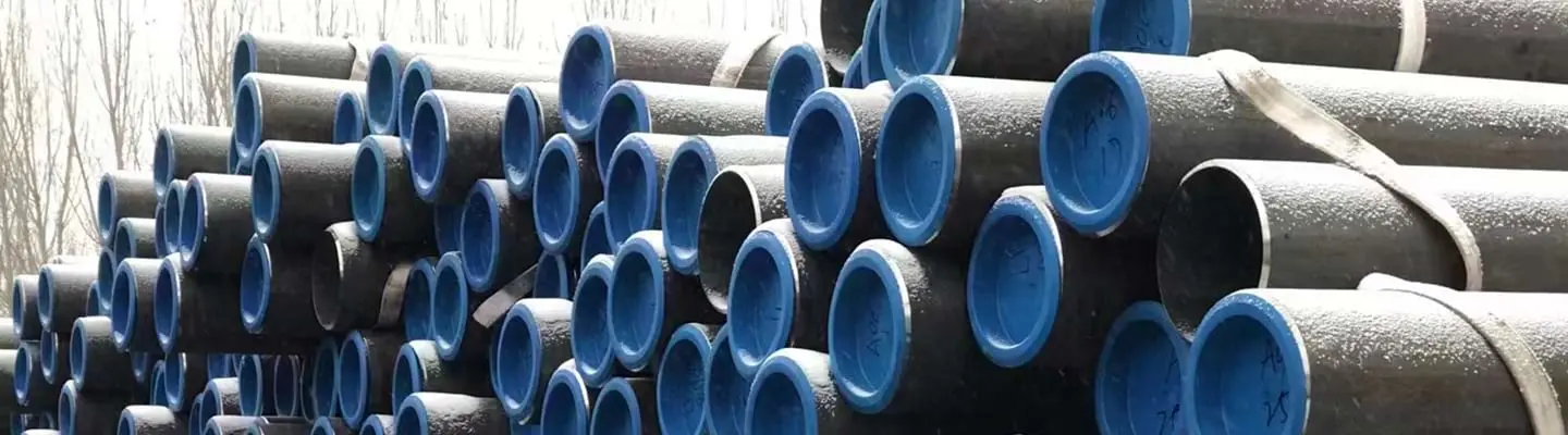
The global push to decarbonize gas infrastructure has placed hydrogen blending at the top of pipeline operators' agendas, but the same steel that handles methane at high pressure behaves differently when hydrogen molecules — and the atomic hydrogen they generate — are present. Hydrogen's small atomic radius allows it to diffuse into the steel lattice, reducing ductility, initiating internal cracks at inclusion sites, and degrading weld zones that would be perfectly acceptable in conventional gas service. These are not theoretical concerns: hydrogen embrittlement failures in high-strength steel components are well-documented across refinery and chemical process industries, and the risk transfers directly to transmission line pipe as H2 concentration increases. Selecting hydrogen-ready line pipe therefore requires going beyond the base API Specification 5L, 46th Edition compliance to address delivery condition, chemistry, toughness, hardness, and weld qualification under a framework governed primarily by ASME B31.12.
ZC Steel Pipe (Zhencheng Steel Co., Ltd.) supplies seamless and LSAW welded line pipe to API Specification 5L, 46th Edition PSL2, including M delivery grades from X65M through X80M with Annex H HIC-resistant chemistry, EN 10204 3.1/3.2 material test certificates, and third-party inspection, serving EPC projects in Africa, the Middle East, South America, and Southeast Asia.
Quick Answer
For hydrogen blending up to roughly 20% H₂ by volume, specify X65M or X70M — API 5L PSL2 with the M (TMCP) delivery condition — plus Annex H chemistry (S ≤ 0.003%, calcium treatment, HIC testing per NACE TM0284), a hardness limit of ≤ 248 HBW across base metal, weld, and HAZ, and Charpy toughness per ASME B31.12. The two make-or-break line items are "M" and "Annex H": leave either off the PO and you can receive fully API-compliant pipe that is not hydrogen-service qualified.
| H₂ blend (by volume) | Typical grade | Key material requirements |
|---|---|---|
| ≤ 5% | Existing X65M PSL2 | Baseline HIC + hardness data; documented fitness-for-service review |
| 5–20% | X65M / X70M, M delivery | Annex H (S ≤ 0.003%), ≤ 248 HBW, ASME B31.12 CVN |
| 20–50% | Project-qualified X65M / X70M | Hydrogen-charged WPS + fracture-mechanics testing |
| Pure H₂ (100%) | Lower grade (X52 / X60) | Full ASME B31.12 Chapter IV qualification |
On an East Africa gas pipeline project, the purchase order correctly specified X65M Annex H. The MTC showed sulfur of 0.008% — more than double the 0.003% Annex H limit. Our receiving inspector caught it during document review. When we traced the issue, the mill had applied the standard PSL2 S limit (0.015%) to this heat, not the Annex H limit. The Annex H requirement was written in the commercial terms but not carried through to the mill's test plan. The pipe was rejected before delivery — but it was close. If the MTC had been reviewed only at the summary level, the S content could have been missed in a column of numbers. For hydrogen-service line pipe, Annex H sulfur compliance must be a named line item on the receiving checklist, not a background assumption.
The Hydrogen Threat: How H2 Degrades Carbon Steel
Carbon steel reacts to hydrogen in several distinct ways depending on temperature, pressure, stress state, and the microstructure of the steel. Understanding each mechanism is essential because they call for different mitigation strategies in material selection and welding procedure qualification.
Hydrogen Embrittlement
Hydrogen embrittlement (HE) occurs when atomic hydrogen — generated by the dissociation of H2 molecules at the pipe wall surface under pressure — diffuses into the steel lattice and accumulates at grain boundaries, dislocation pile-ups, and other high-stress sites. The absorbed hydrogen reduces cohesive strength at these locations, lowering the apparent ductility and fracture toughness of the steel without changing its room-temperature tensile strength as measured in a standard uniaxial test. In service, this means a pipe that meets API 5L tensile requirements can fail at stress intensities well below those predicted by fracture mechanics calculations derived from standard air testing. Susceptibility typically increases with steel strength (yield strength above approximately 550 MPa warrants particular attention), with hydrogen partial pressure, and with decreasing temperature, making winter operating conditions in northern climates or deepwater riser applications especially sensitive.
Hydrogen-Induced Cracking
Hydrogen-induced cracking (HIC) is a distinct phenomenon that does not require an externally applied stress. Atomic hydrogen diffusing through the steel lattice accumulates preferentially at elongated manganese sulfide (MnS) inclusions and banded microstructure regions. The hydrogen molecules recombine at these internal interfaces, generating internal pressure that exceeds the local cohesive strength of the steel and initiating flat, stepwise internal cracks parallel to the pipe wall. In conventional sour gas (H2S) service, HIC is well-characterized under ISO 15156 / NACE MR0175 and API 5L Annex H. The same cracking mode is relevant in high-pressure H2 blending service because the driving force — atomic hydrogen at inclusions — is the same regardless of the hydrogen source. This is why even pipelines not carrying H2S are being specified to Annex H sulfur limits (S ≤ 0.003%) and NACE TM0284 HIC testing for H2 blending projects.
Weld Zone Vulnerability
Girth welds and their heat-affected zones (HAZ) are typically the most hydrogen-sensitive locations in a pipeline. Rapid thermal cycles during welding can produce hard martensitic or bainitic microstructures in the HAZ, particularly in higher-carbon or higher-CE steels. These hard zones — if hardness exceeds approximately 248 HBW — are more susceptible to hydrogen-assisted cracking during service. In addition, welding consumable selection, preheat temperature, interpass temperature control, and post-weld heat treatment (PWHT) all affect the final HAZ hardness and toughness. For hydrogen blending projects, the welding procedure specification (WPS) must demonstrate that the as-welded HAZ hardness meets the project limit, and procedure qualification testing should include hardness traverses and, for higher H2 concentrations, slow-strain-rate or rising step load fracture mechanics tests on weld specimens.
Regulatory and Code Framework
ASME B31.12 "Hydrogen Piping and Pipelines" is the primary design and material qualification code for hydrogen service pipelines. For transmission pipelines carrying hydrogen blends, ASME B31.8 "Gas Transmission and Distribution Piping Systems" applies concurrently; the more restrictive requirement of the two governs material selection, design factor, and inspection. ASME B31.12 introduces material performance factor (MPF) reductions that effectively lower the allowable hoop stress compared with the same pipe in pure methane service, and it includes Chapter IV with specific material qualification requirements that go beyond standard PSL2 compliance.
API Specification 5L, 46th Edition remains the base material standard. For hydrogen service, PSL2 is mandatory — PSL1 does not include the toughness, chemistry, or dimensional tolerances needed for H2 service. Annex H of API 5L defines supplementary requirements for HIC-resistant pipe: sulfur ≤ 0.003%, calcium treatment, through-thickness Charpy V-notch testing, and HIC testing per NACE TM0284. These requirements, originally developed for sour gas (H2S) service, are being applied by project specifications globally to H2 blending projects because the underlying hydrogen damage mechanism is common to both environments.
ISO 15156 / NACE MR0175 governs hardness limits and material requirements for equipment exposed to H2S environments. For pure H2 pipelines, ISO 15156 does not technically apply in its sour service scope, but many project specifications reference its hardness limits — typically ≤ 248 HBW for carbon and low-alloy steels — as a conservative baseline for hydrogen-resistant material selection in non-H2S hydrogen service.
Mechanical Properties for H2-Compatible Line Pipe
The three grades most commonly specified for hydrogen blending mainlines are X65M (L450M), X70M (L485M), and X80M (L555M), all to API Specification 5L, 46th Edition PSL2. The table below shows the full mechanical property envelopes from the API 5L JSON data.
| Property | X65M (L450M) | X70M (L485M) | X80M (L555M) |
|---|---|---|---|
| Yield strength — min | 450 MPa (65,300 psi) | 485 MPa (70,300 psi) | 555 MPa (80,500 psi) |
| Yield strength — max | 600 MPa (87,000 psi) | 635 MPa (92,100 psi) | 705 MPa (102,300 psi) |
| Tensile strength — min | 535 MPa (77,600 psi) | 570 MPa (82,700 psi) | 625 MPa (90,600 psi) |
| Tensile strength — max | 760 MPa (110,200 psi) | 760 MPa (110,200 psi) | 825 MPa (119,700 psi) |
| Y/T ratio — max | 0.93 (D > 323.9 mm) | 0.93 (D > 323.9 mm) | 0.93 (D > 323.9 mm) |
| Delivery condition | M (TMCP) | M (TMCP) | M (TMCP) |
Source: API Specification 5L, 46th Edition, PSL2 mechanical requirements (JSON last updated 2026-05-19).
For hydrogen service, the maximum yield strength is as important as the minimum. A pipe certified to X65M may have an actual yield strength anywhere from 450 to 600 MPa (65,300 to 87,000 psi). Steel at the upper end of that window is structurally more susceptible to hydrogen embrittlement than steel at the lower end. Project specifications for H2 service sometimes narrow the yield window or add supplementary toughness testing to screen for over-strength pipe, particularly when the design operates close to MAOP and the H2 partial pressure is significant.
For the complete PSL1 and PSL2 grade tables, see the API 5L specification tables → and the ASME B36.10M pipe schedule chart →
To calculate design pressure or minimum wall thickness for your pipeline, use the Pipeline Design Calculator →
Wall Thickness Design for H2 Blending — Worked Example
For a natural gas / H2 blend pipeline: X65M, 323.9 mm OD, MAOP = 80 bar (8.0 MPa), ASME B31.8 design factor F = 0.72, weld joint factor E = 1.0, temperature derating T = 1.0
Step 1 — Standard ASME B31.8 wall thickness (pure methane service): t = P × D / (2 × SMYS × F × E × T) t = 8.0 × 323.9 / (2 × 450 × 0.72 × 1.0 × 1.0) t = 2,591.2 / 648 = 4.00 mm
Step 2 — Apply ASME B31.12 material performance factor (MPF) for H2 service: For X65M at 20% H2 blend: MPF ≈ 0.834 (refer to ASME B31.12 Table IX-5A for current values — verify against the edition in use) Effective design factor = F × MPF = 0.72 × 0.834 = 0.600
Step 3 — H2-adjusted wall thickness: t_H2 = 8.0 × 323.9 / (2 × 450 × 0.600) t_H2 = 2,591.2 / 540 = 4.80 mm
Step 4 — Add mill tolerance (API 5L seamless, −12.5%): t_order = t_H2 / (1 − 0.125) = 4.80 / 0.875 = 5.49 mm minimum order wall
Step 5 — Select nearest commercial schedule: For NPS 12 (323.9 mm OD): next standard wall is 6.35 mm (0.250") Specify 6.35 mm minimum wall.
Note: The MPF effectively requires a 20% thicker wall for H2 blending service compared to pure methane at the same pressure. This wall increase is the ASME B31.12 safety margin for hydrogen embrittlement — not a corrosion allowance.
Chemical Composition Requirements
The M delivery suffix is not a formality — it is the single most consequential specification decision for hydrogen-ready line pipe. M delivery (TMCP) locks in C max 0.12% for X65M versus C max 0.18% for X65Q. That 50% reduction in maximum carbon is the primary lever controlling HAZ hardness during girth welding, hydrogen trapping at carbide interfaces, and resistance to hydrogen-assisted cracking. An X65M and an X65Q pipe look identical in the field, have the same OD and wall, and both have "API 5L PSL2" on the MTC. The difference is invisible except on the MTC delivery condition line. This is why "API 5L X65 PSL2" — without "M" — is a hydrogen-service procurement failure waiting to happen.
Chemistry drives hydrogen susceptibility at the microstructural level. The table below shows M delivery chemistry for each grade per API Specification 5L, 46th Edition PSL2.
| Element | X65M (L450M) | X70M (L485M) | X80M (L555M) |
|---|---|---|---|
| C max | 0.12% | 0.12% | 0.12% |
| Si max | 0.45% | 0.45% | 0.45% |
| Mn max | 1.60% | 1.70% | 1.85% |
| P max | 0.025% | 0.025% | 0.025% |
| S max | 0.015% | 0.015% | 0.015% |
| Nb+V+Ti max | 0.15% | 0.15% | 0.15% |
| CE_IIW max | 0.43 | 0.43 | 0.43 |
| CE_Pcm max | 0.25 | 0.25 | 0.25 |
Source: API Specification 5L, 46th Edition, PSL2 chemistry — M delivery condition.
For hydrogen service, the standard PSL2 sulfur limit of 0.015% is insufficient. API 5L Annex H reduces this to S ≤ 0.003%, and calcium treatment is required to modify any residual sulfide inclusions from elongated MnS to spheroidal calcium aluminate forms that are far less effective as hydrogen traps. Phosphorus at its PSL2 limit of 0.025% also contributes to hydrogen trapping at grain boundaries; some project specifications impose P ≤ 0.015% for critical H2 service.
Why M delivery outperforms Q delivery for hydrogen service: The Q (quenched and tempered) versions of these grades achieve their mechanical properties primarily through carbon and alloy additions followed by hardening heat treatment. X65Q carries C max 0.18% versus X65M at 0.12% — a 50% higher carbon ceiling. That additional carbon raises the CE_IIW, increases weld HAZ hardness, and provides more sites for hydrogen trapping at carbide interfaces. The TMCP process used for M delivery achieves equivalent or superior strength through controlled deformation at reduced temperatures, enabling the lower carbon content that is the single most important chemistry lever for hydrogen resistance. The finer austenite grain size produced by TMCP also yields better low-temperature toughness, which is particularly valuable in cold-climate pipeline applications where hydrogen diffusivity decreases but brittleness risk rises.
Blending Scenarios: 5%, 10%, 20%, and 100% H2
Hydrogen blending codes and material qualification thresholds are evolving rapidly. The blend concentration limits and hardness values cited in this section reflect industry consensus and ASME B31.12 guidance as of 2026. Always verify against the current edition of ASME B31.12, applicable national pipeline safety regulations, and the project owner's hydrogen qualification programme before finalising material specifications.
The H2 concentration in the blend determines which material requirements apply and how conservatively each must be interpreted.
Up to 5% H2 by volume is generally treated by European project operators as a range where no material modifications beyond standard PSL2 are required for modern pipelines already built with M delivery pipe and Annex H chemistry, pending a documented fitness-for-service review. Even at this low concentration, operators are advised to obtain baseline HIC and hardness data on representative weld and base metal samples before beginning H2 injection.
5% to 20% H2 by volume is the range where most active blending trials and regulatory guidance are currently concentrated. Industry consensus as of 2026 treats X65M PSL2 pipe with Annex H HIC chemistry as compatible with up to approximately 20% H2 by volume, subject to qualification testing on project-specific material heats — note that no single normative document currently establishes this threshold universally. X70M in this range requires additional evidence of adequate fracture toughness under hydrogen partial pressure. Wall thickness selection should be reviewed because increasing wall thickness at the same MAOP reduces hoop stress as a fraction of yield strength, directly lowering the driving force for hydrogen-assisted fracture.
20% to 50% H2 by volume moves into territory where most standards bodies and regulators currently require project-specific material qualification programs. ASME B31.12 material performance factors impose additional design margin, and weld procedure qualification testing must include hydrogen-charged specimens. X80M enters a higher-scrutiny zone at this concentration and should be used only with comprehensive hydrogen-charging fracture mechanics test data.
Pure H2 transmission (100%) falls under the full scope of ASME B31.12. Industry and research experience has historically favored lower-strength grades such as X52 or X60 for dedicated hydrogen transmission pipelines to minimize hydrogen embrittlement risk. At these concentrations, the base metal, girth welds, fittings, and all appurtenances require individual qualification under the ASME B31.12 Chapter IV framework.
When NOT to Use X80M for Hydrogen Blending
| Scenario | Risk | Correct Approach |
|---|---|---|
| H2 blend above 10% without project-specific qualification | X80M has highest strength and highest HE susceptibility of the three common grades; industry data above 10% H2 is limited | Use X65M or X70M for blends above 10% unless X80M has been qualified with hydrogen-charged fracture mechanics tests |
| X65M or X70M specified without M suffix | Mill supplies Q or N delivery with higher CE and HAZ hardening risk | Always write "L450M / X65M, TMCP delivery" — never just "X65 PSL2" |
| Annex H omitted from sour H2 blending PO | S up to 0.015% allows HIC at MnS inclusion sites under H2 partial pressure | Invoke Annex H explicitly on every H2 blending PO regardless of H2S content |
| HAZ hardness not tested on WPS qualification | Weld procedure may produce HAZ > 248 HBW that is invisible without hardness traverse | Mandate full Vickers hardness traverse (base/HAZ/weld/HAZ/base) in WPS qualification for hydrogen service |
| No TPI hold at HIC test stage | Mill may accept borderline HIC results administratively without engineer review | Specify a TPI hold point at the HIC test — inspector must witness raw crack measurements, not just final acceptance report |
| PWHT omitted for heavy wall pipe | Heavy-wall girth welds retain high residual stress that drives H2 diffusion toward the HAZ | For wall thickness above approximately 19 mm, evaluate PWHT requirement for hydrogen service — residual stress reduction is an independent benefit beyond hardness control |
Weld and HAZ Considerations
Girth welding of hydrogen-ready line pipe requires the same discipline applied to sour service welding, with additional attention to hardness control across the full weld cross-section. The following points summarize the key requirements.
Preheat and interpass temperature must be set to ensure the HAZ cools slowly enough to avoid martensite formation. For X65M with CE_Pcm ≤ 0.25, the minimum preheat per AWS D1.1 or project specification is typically in the range of 50–100°C depending on wall thickness and ambient temperature, but hydrogen service projects often apply the higher end of this range as a conservative measure even for thin-wall pipe.
Hardness traverses across the weld, fusion line, and HAZ must be performed as part of procedure qualification. The commonly cited limit of ≤ 248 HBW applies to all weld zones, not just the base metal. Any localized hardness exceedance — even a single indentation above the limit in the HAZ — should trigger metallurgical review and potentially a modified WPS before the procedure is accepted for hydrogen service.
PWHT applicability depends on wall thickness and project design code. For thin-wall pipe (typically ≤ 19 mm), PWHT is not always required if hardness limits can be met through welding parameter control. For heavy-wall transmission pipe with significant restraint, PWHT may be the most reliable method of achieving uniform hardness below the hydrogen service limit while also reducing residual stress — an additional benefit because residual tensile stress accelerates hydrogen diffusion toward critical locations.
Weld inspection for hydrogen service projects should include 100% automated ultrasonic testing (AUT) of girth welds in addition to radiographic testing, since planar defects such as lack of fusion or cold cracking are more critical in hydrogen service than volumetric porosity. Acceptance criteria for weld defects should reference fracture mechanics-based ECA (engineering critical assessment) rather than workmanship criteria alone.
Purchase Order Guidance
A technically compliant purchase order for hydrogen-ready line pipe must specify several items beyond standard API 5L PSL2 compliance. Omitting any one of them can result in receiving pipe that is fully certified to the base standard but inadequate for hydrogen service.
Procurement trap — M suffix and Annex H omitted:
Wrong PO: "API 5L PSL2 X65, 323.9 mm × 14.3 mm, seamless, EN 10204 3.2."
What ships: X65Q (or N) — fully API 5L compliant, C max 0.18%, S up to 0.015%, no HIC test data, no CE Pcm requirement. The pipe arrives with a valid MTC showing all standard PSL2 requirements met. It is not hydrogen-service qualified. HAZ hardness on girth welds may reach 280–310 HBW. At 20% H2 blend, HAZ cracking risk is real within the first decade of service.
Correct PO: "API Specification 5L, 46th Edition, PSL2, Grade L450M / X65M, TMCP delivery. Annex H supplementary requirements apply: S ≤ 0.003%, calcium treatment, HIC testing per NACE TM0284 (CSR ≤ 0.015, CTR ≤ 0.0015, CLR ≤ 0.005). Hardness ≤ 248 HBW on base metal and weld seam (LSAW). CE Pcm ≤ 0.25 — state on MTC. Charpy V-notch at [specify °C per project minimum design temperature]. EN 10204 3.2. TPI hold point at HIC test stage."
The M delivery trap is the most common procurement error. If the purchase order states only "API 5L PSL2 X65" without explicitly specifying the M delivery condition, a supplier may ship X65Q — quenched and tempered pipe with C max 0.18% and higher CE. X65Q is fully API 5L compliant and indistinguishable by grade designation alone, but its higher carbon content makes it significantly more susceptible to HAZ hardening and hydrogen embrittlement. Always write "L450M / X65M, TMCP delivery" on the PO line item.
Annex H omission is the second major trap. Standard PSL2 carries S ≤ 0.015% and does not require HIC testing. If Annex H is not explicitly invoked, you will receive PSL2 pipe with four times the allowable sulfur content and no HIC test data. For hydrogen service, specify: "Annex H supplementary requirements apply: S ≤ 0.003%, calcium treatment per mill procedure, HIC testing per NACE TM0284 — acceptance criteria CSR ≤ 0.015, CTR ≤ 0.0015, CLR ≤ 0.005."
Hardness documentation must be specified at the pipe body, weld seam (LSAW pipe), and — if weld procedure qualification records are available — HAZ. Require hardness values on the EN 10204 3.2 MTC, not just a statement of compliance.
Charpy V-notch requirements must reference the applicable ASME B31.12 table and temperature. Leaving CVN unspecified means the pipe will be tested at 0°C to API 5L default requirements, which may be insufficient for cold-climate operation or for the toughness margin needed at elevated hydrogen partial pressures.
Third-party inspection should include a hold point at the HIC test stage, not just final dimensional and hydrostatic testing. This allows the TPI inspector to review raw HIC test specimens and crack measurements before pipe is released, providing a defense against acceptance of borderline results that might otherwise pass through administrative review alone.
ZC Steel Pipe can supply L450M / X65M and L485M / X70M seamless and LSAW line pipe with Annex H chemistry, NACE TM0284 HIC test reports, EN 10204 3.2 certificates, and third-party inspection coordination for hydrogen blending projects in the Middle East, Africa, South America, and Southeast Asia. Enquiries for PSL2 M delivery line pipe with hydrogen service documentation packages should be directed to Hazel Wang at hazel.w@zcsteelpipe.com.
Failure Modes
Failure Mode 1 — Q delivery with high CE installed in H2 blending mainline
Mechanism: X65 is ordered without the M suffix. The mill ships X65Q with C = 0.17%, CE Pcm = 0.27. During field girth welding with standard preheat (50°C for 14.3 mm wall), the HAZ cools rapidly through the martensite range, producing a hardened zone with peak hardness of 285 HBW — 37 HBW above the 248 HBW hydrogen service limit. When the line is commissioned with 15% H2 blend at 85 bar, atomic hydrogen diffuses preferentially into the hardened HAZ. Hydrogen-assisted cracking initiates at a weld-root discontinuity within 18 months of service.
Diagnostic: Inline inspection detects a circumferential indication at a girth weld in a known dogleg location. Excavation and weld section show HAZ cracking with hydrogen blistering. Hardness traverse of the weld section confirms HAZ peak hardness 280–290 HBW. MTC review reveals delivery condition Q, not M.
Fix: Reject any X65/X70/X80 pipe for hydrogen blending service where the MTC does not explicitly state M delivery condition and CE Pcm ≤ 0.25. Add MTC review for delivery condition as a mandatory receiving inspection step, not a background check.
Failure Mode 2 — Annex H S limit not enforced; HIC at MnS inclusions
Mechanism: The PO specifies Annex H in the narrative but does not add a specific S ≤ 0.003% line item in the chemical requirements section. The mill interprets the standard PSL2 S limit (0.015%) as governing. The delivered pipe has S = 0.009% — six times the Annex H limit. MnS inclusions are present at the standard PSL2 density. Under 20% H2 partial pressure, atomic hydrogen accumulates at the elongated MnS inclusions. Stepwise HIC cracks form parallel to the pipe wall. Over 5 years, the cracks coalesce and the wall is perforated at a location 80 m from the nearest weld.
Diagnostic: Gas loss detected. Excavation reveals internal planar cracks at mid-wall, consistent with HIC morphology. MTC shows S = 0.009% — within PSL2 limits but exceeding the Annex H limit. No HIC test results are on the MTC because Annex H was not enforced.
Fix: For every H2-service pipe order, Annex H must be a hard requirement with explicit S ≤ 0.003%, calcium treatment, and NACE TM0284 HIC test results on the MTC. The MTC reviewer must check the S value and confirm HIC test data is present before accepting the heat.
Failure Mode 3 — No TPI hold at HIC test; borderline result accepted
Mechanism: HIC testing is performed at the mill without a TPI hold point. The mill's own inspector measures crack dimensions and records CLR = 0.006 (just within the 0.005 acceptance criterion... after rounding). The pipe is shipped with an Annex H MTC. Six months later, during a project audit, the raw crack measurement data is reviewed — actual CLR was 0.0058, which rounds to 0.006 but the acceptance criterion of 0.005 was not met. The pipe has been installed.
Diagnostic: Post-installation document audit finds raw HIC measurement records showing CLR marginally exceeding the acceptance criterion before rounding. The mill's inspector accepted the result using rounded values.
Fix: For all H2-service line pipe, specify a TPI hold point at the HIC test. The TPI inspector must be physically present during crack measurement, review the raw (unrounded) measurements, and sign the acceptance record. Do not rely on the mill's own inspector for self-certification of Annex H compliance.
Frequently Asked Questions
What makes a pipeline 'hydrogen-ready'?
A hydrogen-ready pipeline is one whose base material, welds, and heat-affected zones have been selected, tested, and qualified to resist hydrogen embrittlement and hydrogen-induced cracking at the intended H2 partial pressure. This typically means specifying PSL2 line pipe with the M (TMCP) delivery condition, sulfur content at or below 0.003%, calcium treatment for inclusion shape control, hardness limits commonly at or below 248 HBW, and project-specific Charpy V-notch toughness requirements aligned with ASME B31.12 Table IV-B.2.
Can existing X65 PSL2 gas pipelines carry hydrogen?
Existing X65 PSL2 pipelines built with M delivery condition, Annex H chemistry, and adequate toughness are generally considered by industry consensus to be compatible with blends up to approximately 20% H2 by volume, subject to a documented fitness-for-service assessment and qualification testing. Note that no single normative document currently establishes a universally accepted threshold — the evaluation must be project-specific. Pipelines built to lower PSL levels, with Q delivery, or with unknown weld histories require more conservative evaluation before any H2 introduction.
Why is M delivery preferred over Q delivery for hydrogen service?
The M (thermomechanical) delivery condition produces a finer austenite grain structure and a lower carbon equivalent (CE_Pcm ≤ 0.25 for X65M vs a typically higher effective CE for X65Q at C max 0.18%) because TMCP achieves the required strength through controlled rolling rather than alloying. The finer grain size and lower carbon content translate directly into higher resistance to hydrogen diffusion, better low-temperature toughness, and a lower risk of heat-affected zone hardening during girth welding — all critical for hydrogen service.
What sulfur content is required for HIC-resistant line pipe?
API Specification 5L, 46th Edition Annex H specifies a maximum sulfur content of 0.003% (30 ppm) for HIC-resistant pipe, compared with the standard PSL2 limit of 0.015%. At sulfur levels above approximately 0.003%, elongated manganese sulfide (MnS) inclusions provide preferential sites for atomic hydrogen to accumulate and initiate stepwise internal cracks. Most hydrogen blending projects apply the Annex H sulfur limit regardless of H2S content because atomic hydrogen from H2 gas can also accumulate at inclusions under high pressure.
Does X80 need special qualification for hydrogen blending?
Yes. X80M (L555M) has the highest strength of the three grades commonly considered for hydrogen-blended mainlines, and higher strength generally correlates with increased susceptibility to hydrogen embrittlement. ASME B31.12 typically requires additional material qualification steps for higher-strength steels used in hydrogen service, and most project specifications require project-specific fracture toughness and slow-strain-rate tensile testing on both the base metal and welds before X80M is accepted for H2 blending above 10% concentration.
What is the maximum allowable hydrogen partial pressure for X65 PSL2?
ASME B31.12 does not publish a single blanket partial pressure limit for X65 PSL2; the allowable partial pressure is determined by the design factor, wall thickness, and material qualification data applicable to the specific project. Industry guidance and ongoing research programs generally treat 20% H2 by volume in a natural gas blend at typical transmission pressures (70–100 bar) as the upper boundary for existing X65M infrastructure pending further qualification, but project owners and operators must confirm compliance with ASME B31.12 and their regulatory authority.
What standard governs hydrogen pipeline design?
ASME B31.12 'Hydrogen Piping and Pipelines' is the primary design code for dedicated hydrogen pipelines and hydrogen blending scenarios in the United States and is increasingly referenced internationally. For blend pipelines that also fall under gas transmission jurisdiction, ASME B31.8 'Gas Transmission and Distribution Piping Systems' applies concurrently, and the more restrictive requirement of the two governs. Material qualification must satisfy both codes as well as the applicable national pipeline safety regulations for the project country.
What should a purchase order include for H2-compatible line pipe?
A purchase order for hydrogen-compatible line pipe should explicitly state: API Specification 5L 46th Edition PSL2 with M delivery condition; the specific grade designation (e.g., L450M / X65M); sulfur maximum 0.003% with calcium treatment; HIC testing per NACE TM0284 with acceptance criteria; hardness limit on base metal, weld, and HAZ (commonly ≤ 248 HBW as of current practice); minimum Charpy V-notch energy per ASME B31.12 Table IV-B.2; EN 10204 3.2 material test certificates; and a third-party inspection hold point at the mill before pipe release.